Healtech Brake light pro

Joined
Sep 11, 2017
Messages
11
Location
London
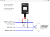
Hi everyone. Bought Healtech Brake light pro BLP what is brake light modulator/flasher. has anyone got one? Don’t know how to attach it to my ST1300, requesting some advice. It’s designed to be attached to 2 wires (brake light and ground). Under the fender I have 6 wires. My quick idea was to tap left side green/yellow brake light wire and black ground. Healtech said I can’t tap in just one side. Healtech said it‘s important to make the connections at the rear light assemble before the junction splits in 6 wires (left, right rear brake bulbs) so both bulbs will be working with the BLP. their manual:
93C0FA99-6302-4F20-B73E-4C670DBBA345.png
’Anna’sDad’ posted: The brake lamp circuit does use a Green/Yellow conductor, actually the circuit uses four Green/Yellow conductors.
The four Green/Yellow conductors:
  1. Front brake lamp switch.
  2. Rear brake lamp switch.
  3. Right-side brake lamp.
  4. Left-side brake lamp.
‘Anna’sDad‘ posted the harness. In this photo the location of the four Green/Yellow conductors can be seen, the connection is wrapped with blue tape.
9CEA841F-0EA0-4803-A981-6AA5C10A3248.png
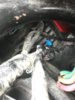
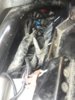
For me it means there is no single green/yellow wire I can tap in? What is the recommended solution? This photo is view from under the fender - 6 wires follow to the two rear bulbs.090FC2AC-2B4F-4258-9E14-33C069589B9C.jpeg
 
Last edited:

st11ray

2006 ST1300
Joined
Jul 29, 2007
Messages
2,735
Location
charlotte, nc
Bike
'06 ST1300
STOC #
7189
I dropped the rear fender and connected my Hyperlites and Whelen light strip to the wires going into each bulb. It's worked well for me for years. I don't know if that helps or not?
 
Joined
Sep 22, 2015
Messages
1,287
Location
Wasaga Beach, Ont. Canada
Bike
'04 ST1300 Blue STar
I did the same as st11ray,,, for my Admore rear brake and signals light bar. They have the same size led bar now,, that includes an accelerometer which activates brake lighting during engine braking,,,, cheers,, CAt'
 

dduelin

Tune my heart to sing Thy grace
Site Supporter
Joined
Feb 11, 2006
Messages
9,680
Location
Jacksonville
Bike
GL1800 R1200RT NC700
2024 Miles
008131
STOC #
6651
The wiring diagram for USA bikes shows just one G/Y wire leading to the taillight/brake light fixture. It splits to feed the two brake lights. You can tap G/Y there like st11ray and I did or find one of the G/Y leaving the front or rear brake light switch. If the unit is designed to work off brake light power and common ground you only need these two connections.
 
Joined
Aug 21, 2018
Messages
6,773
Location
Richmond, VA
Bike
'01 & '96 ST1100s
STOC #
9007
  1. Front brake lamp switch.
  2. Rear brake lamp switch.
  3. Right-side brake lamp.
  4. Left-side brake lamp.
1 and 2 come from the front of the bike, but should combine into a single wire to go to the back of the bike, then split into 3 and 4 for the two bulbs. In your second pic, where you see the two green/yellow wires, follow them away from the bulbs. They should join into a single wire, possibly near a plug, which is where you should make your cut and connections.

It sounds like your description of four wires comes from the wiring diagram, and not the actual wires. Let us know whether you find what I just described.
 
Joined
Aug 21, 2018
Messages
6,773
Location
Richmond, VA
Bike
'01 & '96 ST1100s
STOC #
9007
The wiring diagram for USA bikes shows just one G/Y wire leading to the taillight/brake light fixture. It splits to feed the two brake lights. You can tap G/Y there like st11ray and I did or find one of the G/Y leaving the front or rear brake light switch. If the unit is designed to work off brake light power and common ground you only need these two connections.
His module interrupts the bike's brake-light wire, because it flashes the bike's brake lights, not a separate auxiliary light.
 

dduelin

Tune my heart to sing Thy grace
Site Supporter
Joined
Feb 11, 2006
Messages
9,680
Location
Jacksonville
Bike
GL1800 R1200RT NC700
2024 Miles
008131
STOC #
6651
His module interrupts the bike's brake-light wire, because it flashes the bike's brake lights, not a separate auxiliary light.
Ok, there’s still one G/Y wire in the harness passing through open space under the luggage rack above the taillight assembly. Tap it there. It powers both brake light bulb filaments. I installed a similar module to flash a separate LED light bar and tapped the G/Y there in the tail cone space.
 
Last edited:

st11ray

2006 ST1300
Joined
Jul 29, 2007
Messages
2,735
Location
charlotte, nc
Bike
'06 ST1300
STOC #
7189
I didn't cut anything. Just used weatherproof PosiTaps. No problem in the 13 years they've been in there.
 
Joined
Aug 21, 2018
Messages
6,773
Location
Richmond, VA
Bike
'01 & '96 ST1100s
STOC #
9007
I didn't cut anything. Just used weatherproof PosiTaps. No problem in the 13 years they've been in there.
His module interrupts the bike's brake-light wire, because it flashes the bike's brake lights, not a separate auxiliary light.
 

ST Gui

240Robert
Site Supporter
Joined
Sep 12, 2011
Messages
9,280
Location
SF-Oakland CA
Bike
ST1300, 2010
Here's a video on installing the BLP on an FZ-1. It won't address what wires go where but that's been covered already. 2:55 shows the brake light interrupt concept.


The hallmark of the BLP is the programability of flash patterns. Choosing a pattern is a process.
 
OP
OP
Joined
Sep 11, 2017
Messages
11
Location
London
Ok, there’s still one G/Y wire in the harness passing through open space under the luggage rack above the taillight assembly. Tap it there. It powers both brake light bulb filaments. I installed a similar module to flash a separate LED light bar and tapped the G/Y there in the tail cone space.
I will try to find that,it would be ideal. I had a look from the top of the bike under the seat. There is no way I will unwrap the main harness but I can see few green/yellow wires Leaving main harness. I think I will take computer box out, it will be easier to see.
Another option I found - Under number plate I have an extra 3red led light with connector what is not attached. Probably it is brighter than my rear brake LED’s Swithcbacks from Lightenupgrade. I could make my wire with same connector, add Healtech Brake LightPro device to my wire and get power by tapping (positap) in one of the rear brake lights. This is an ex emergency service bike, that extra 3red led light (sae type) probably was engaged with one of switches from right handlebar. I have couple unattached connections under the seat.
O.K.new day: from under the seat I removed aside two computer boxes to have a better access to the green/yellow wire what I need. I hoped to find it will merge into one because there are two gr/yell wires coming from brake bulbs. I would attach my brake gadget there. What I saw is both gr/yell wires go from brake lights and hides inside the big wiring loom. I marked that cable what holds both wires with blue sellotape. From bottom of the bike were brake lights are located those two gr/yell wires (and few more) are wrapped in black coat cable, so this cable goes up through the gap in plastics. There it joins another wiring cable and disappears in big wiring loom. It means unless I unwrap whole wiring loom I will not find where both gr/yell wires merge into one. I did not see any single and lonely gr/yell wires where I could tap and use as a brake light main wire. This all brake light gr/yell wire business is funny because in wiring diagram its clearly shown that two wires leave br.lights and merge in one. BUT I CAN’T FIND WHERE. I will tap two my wires in both gr/yell near br.lights, I will merge them in one, add my gadget to my wire and attach my wire with gadget to auxiliary brake light under the number plate. I wonder how all that is going to work...
 

Attachments

Last edited:
OP
OP
Joined
Sep 11, 2017
Messages
11
Location
London
Here's a video on installing the BLP on an FZ-1. It won't address what wires go where but that's been covered already. 2:55 shows the brake light interrupt concept.


The hallmark of the BLP is the programability of flash patterns. Choosing a pattern is a process.
I saw the video Before I bought the device. I thought it will be that easy to attach as shown in video, silly me, forgot it’s 18year old wiring design...
 
Joined
Aug 21, 2018
Messages
6,773
Location
Richmond, VA
Bike
'01 & '96 ST1100s
STOC #
9007
need time to figure this out, will post the result
If all else fails, fly me to you, and I'll help you.


Seriously, at some point, those separate green/yellows should merge into a single wire from the front, unless the harness was modified for individual operation of each brake-light bulb for emergency use.
 
Joined
Nov 1, 2009
Messages
387
Location
North Plainfield, NJ
Bike
'06 ST1300A
Seriously, at some point, those separate green/yellows should merge into a single wire from the front, unless the harness was modified for individual operation of each brake-light bulb for emergency use.
Should is the key word, unfortunately Honda chose to run one conductor per brake lamp circuit component.

Thus a conductor for each of the brake lamp switches, and a conductor for each of the brake lamp bulbs.

Yep, four components, four conductors, and they all join together somewhere in the midst of the wire harness.

This was discussed some time ago, here's the post from 2013.
 

ST Gui

240Robert
Site Supporter
Joined
Sep 12, 2011
Messages
9,280
Location
SF-Oakland CA
Bike
ST1300, 2010
IIRC there's only one 12+ going into each of the bulbs' sockets for the brake light. What's the downside of cutting each wire somewhere short of the socket and combining them into 1 feed and 1 load connection and wiring in the BLP at that point.

I tend not to tap into or cut factory wiring lest I do something that causes my fiery death. But there's no choice here. So it seems to be a matter of cutting 1 wire vs 2. If viable I'd say that outweighs digging into a loom somewhere.

The only more advantageous option might be if there were one connector set somewhere that feeds both bulbs. Then matching connectors could be added to the BLP so it could be removed and the original harness integrity maintained for whatever advantage that might offer.


edit:
I will tap two my wires in both gr/yell near br.lights, I will merge them in one, add my gadget to my wire and attach my wire with gadget to auxiliary brake light under the number plate. I wonder how all that is going to work...
Missed that. I think that's a better way to go only because I think your white whale is buried under wire wrap. Having said that you'll now probably find it isn't. :D

kris007 said:
Under number plate I have an extra 3red led light with connector what is not attached. Probably it is brighter than my rear brake LED... I could make my wire with same connector, add Healtech Brake LightPro device to my wire and get power by tapping (positap) in one of the rear brake lights
Personally, I think this is a far better solution. It's a guess that LED is an EMS-level module (which usually aren't left on ex-police motors so maybe this was overlooked).

But going this route means the factory brake lights are unmolested and you have a visually discrete brake light that's only a brake light. I think this increases conspicuity over lights that or dimmer for tail and brake light functions and is simpler. BTW - what's the purpose of switchbacks as tail/brake lights in the 1300?
 
OP
OP
Joined
Sep 11, 2017
Messages
11
Location
London
Hi everyone, thank’s to you I finished my “mission impossible”. Straight after night shift, without any sleep I rushed to get the brake light flasher device installed. I had lot of information but the most valuable bit was Anas’Dad schematics he pointed out attaching similar device In forum back in 2013. Without schematics I wouldn’t be that confident to take up this job yet. My plan was as per schematics to cut the original brake light cable and attach flasher device and also wire in auxiliary 3LED light. I used few posi-taps and 3M UY2 connector (supplied with the device). Because I’m not sure how resistant connectors are to the moisture I figured out to play safe. I did not want to take the slightest risk loosing brake light at some point later. I chose not to cut original wires. When first time I took the rear fender off I found 3LED red light, it had cable with some connector hanging there. I attached flasher to my auxiliary 3LED red light! and made it flashing extra brake light.
First I tapped in both original gr/y brake light wires (after they leave from brake lights) connecting left side and right side brake light wire with ‘my wire’. I connected flashers red wire by tapping in ‘my wire’. I connected flashers green wire to 3LED light ‘to be’ positive wire. I merged flashers ground wire with 3LED ground wire and tapped in bike’s brake light green ground wire. I started my bike, pressed brake and 3LED auxiliary light did not work... Checked connectors I found the fault - it was 3M connector I had to attach better. So second time I turned bike on everything went as planned, Healtech Brake light pro flasher attached, auxiliary LED’s flashing whan applied brake. Proud of myself as never dealt with electrics before. Let’s see how long it will last. Not sure if it would be better visual effect with flashing original brake lights as well, but if I want to I can cut the wires and install it. I would better leave it to professional with good soldering skills weather sealing connections properly.
Thank you guys for your input and advice, special thank’s to Ana’sDad!
P.S. I think lack of sleep and last minute change of plan to play safe messed up my brain... or un experience with electrics. As ST Guy said (I read it after install) I believe when connecting device’s red wire, I did not need ‘my wire’. Instead of making ‘my wire’ by tapping in both gr/y wires all I had to do is - connect flashing device’s red wire to one of brake light gr/y wires by tapping in because it still would deliver 12V what my device requires. For some reason I was worried I have plenty of posi-taps but no posi-twist connectors to sort out wiring and did rush a bit as well. But it works, that’s most important for me.
 
Last edited:

fnmag

R.I.P. - 2020
Rest In Peace
Joined
Mar 21, 2009
Messages
1,416
Location
Desert Southwest
Bike
'06 ST1300/Burgmn400
Hi everyone, thank’s to you I finished my “mission impossible”. Straight after night shift, without any sleep I rushed to get the brake light flasher device installed. I had lot of information but the most valuable bit was Anas’Dad schematics he pointed out attaching similar device In forum back in 2013. Without schematics I wouldn’t be that confident to take up this job yet. My plan was as per schematics to cut the original brake light cable and attach flasher device and also wire in auxiliary 3LED light. I used few posi-taps and 3M UY2 connector (supplied with the device). Because I’m not sure how resistant connectors are to the moisture I figured out to play safe. I did not want to take the slightest risk loosing brake light at some point later. I chose not to cut original wires. When first time I took the rear fender off I found 3LED red light, it had cable with some connector hanging there. I attached flasher to my auxiliary 3LED red light! and made it flashing extra brake light.
First I tapped in both original gr/y brake light wires (after they leave from brake lights) connecting left side and right side brake light wire with ‘my wire’. I connected flashers red wire by tapping in ‘my wire’. I connected flashers green wire to 3LED light ‘to be’ positive wire. I merged flashers ground wire with 3LED ground wire and tapped in bike’s brake light green ground wire. I started my bike, pressed brake and 3LED auxiliary light did not work... Checked connectors I found the fault - it was 3M connector I had to attach better. So second time I turned bike on everything went as planned, Healtech Brake light pro flasher attached, auxiliary LED’s flashing whan applied brake. Proud of myself as never dealt with electrics before. Let’s see how long it will last. Not sure if it would be better visual effect with flashing original brake lights as well, but if I want to I can cut the wires and install it. I would better leave it to professional with good soldering skills weather sealing connections properly.
Thank you guys for your input and advice, special thank’s to Ana’sDad!
P.S. I think lack of sleep and last minute change of plan to play safe messed up my brain... or un experience with electrics. As ST Guy said (I read it after install) I believe when connecting device’s red wire, I did not need ‘my wire’. Instead of making ‘my wire’ by tapping in both gr/y wires all I had to do is - connect flashing device’s red wire to one of brake light gr/y wires by tapping in because it still would deliver 12V what my device requires. For some reason I was worried I have plenty of posi-taps but no posi-twist connectors to sort out wiring and did rush a bit as well. But it works, that’s most important for me.
Glad you sorted it out.
Have a good summer.
 

ST Gui

240Robert
Site Supporter
Joined
Sep 12, 2011
Messages
9,280
Location
SF-Oakland CA
Bike
ST1300, 2010
I attached flasher to my auxiliary 3LED red light! and made it flashing extra brake light.
Way to go! Figuratively and literally! A path - I think - of least resistance. Congratulations on your mod!

kris007 said:
Checked connectors I found the fault - it was 3M connector
This is why many of us do not like those 3M Scotch Lock connectors. If you have a spare Positap you use it in place of that 3M connector.

kris007 said:
Not sure if it would be better visual effect with flashing original brake lights as well
I've often said you should have at least one dedicated brake light just like cars that have combined tail/brake lights have a center high mount stop light (CHIMSL). It's off/brighter/off hit the brakes unlike tail/brake light that are bright/brighter/bright And it flashes.

Over time those 3M connectors tend to fail at least in my experience. Should something happen to any of your connections that one brake light would be OOC but your factory brake lights will still function properly.

Sometime during the day and night have someone activate the brakes while you stand back and check out your lights. LEDs in the tail light section don't fully illuminate the enclosure as does the factory incandescents. Using an actual LED lamp assembly is better and especially if it's an EMS type LED is even mo bettah.

Pro Tip: proper manners dictate you post some pics and a video if possible so we can appreciate your handiwork! :D Congratulations on your mod!
 
Last edited:
Top Bottom