Your first picture:

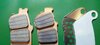
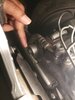
That bolt is the rear caliper bracket stopper bolt. It screws into the swinging arm and slips through an oval shaped hole in the caliper bracket.
It stops the bracket from rotating around the axle when the brakes are applied. This has a torque of 69Nm, it is an ALOC bolt and the manual says to replace with new. I will clean mine up, apply some fresh loctite and re-use it a few times, as my tyres are changed every 5000 miles. But I always have a brand new one in stock, and the manual says to replace with new. I apply a smear of moly paste to the shaft ( not the threads), as it moves against the elongated hole with the different expansion rates of the bracket compared to the swinging arm.
When refitting, this bolt must be secured before the axle bolt is tightened.
----------
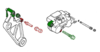
Your Second Picture - The Main Caliper Slider Pin
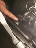
This bolt is the main caliper slide pin. The green one in my diagram and is the one that is incorrectly labelled as requiring a torque of 69Nm in the manual. It is bolted onto the caliper itself, and generally, there is no need to remove it. It slides into the small rubber boot that is fitted to the bracket. The correct torque for this is 27Nm.
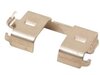
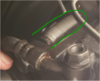
The smaller extract you can see the part of the caliper bracket where the pin slides in - outlined in green. The rubber boot is just visible at the open end of the green loop.
To remove the caliper, you need to remove the axle nut, remove the brake pads, remove the stopper bolt, top photo.
Push the axle part way through from the left - enough to clear the bracket, and lift the bracket and caliper up. It is restricted by the brake hoses. Be careful not to strain them. You can then slide the caliper away from the bracket. The caliper has to stay supported due to the hoses. The bracket comes off completely.
I know you have done some of this, but removing that main slider pin can be problematic.
Quite a few people on here have had problems with the bolt being cross-threaded and then not being parallel to the other slider pin - leaving the caliper unable to move freely towards and away from the brake disc. A posible reason for this may be due to thread damage casued by a previous owner using the wrong torque value on the diagram of 69Nm. Later versions of the manual may have corrected this - but the 2003, 2004 version is widely available (illegally) on line and that version contains the same error on the diagram as my official printed version.
If you do remove it - then when refitting put in the bolt up to the point where you would start to screw the bolt in, but instead, turn it gently anticlockwise. By gently holding the bolt agains the threads you can feel the point where the thread starts as you turn. The bolt 'clicks' as it drops by something around a mm - depending on the distance between the threads. At that point you can turn the bolt clockwise with your fingers with little chance of it cross threading.
I know some people will remove the caliper by removing the two slider pins. I don't do that and never have - mainly becasue I don't need to - I have to take my back wheel off every 5,000 miles for new tyres anyway, and for that I need to remove the bracket. But also - I have big hands and fingers and those bolts look awkward to replace.
For completeness and reference - the torque settings tables at the start of each chapter, and reproduced together for the entire bike in section 1, provide additional information not always found in the text.
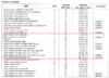
The notes refer to a not-so-easy-to-find table at the start of the torque value section P 1-12 in mine.
So Note 2 applies to the sub-slide pin (the one screwed into the bracket) - Apply locking agent.
The 'New' icon on the diagram I copied earlier - also seems to apply to the stopper bolt, not to the main slide pin.