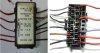
Or, does anyone have a close-up pic of the back of the fuse block? (non-ABS)
I have a fuse block chopped out of a wiring harness with leads still attached. I haven't got a clue which model it is from, none of the wiring diagrams in the manual that I have access to match the layout of the fuses. But it is definitely the standard non-ABS model and the wire colours match the colours for all standard models.
There is one red wire in for the clock.
There are 3 red/black wires in: +12V from ignition switch - presumably connected together at some point. Note the bus bar between the top two fuse locations and between the 3rd and 4th fuse locations, so 5 fuses are powered from the ignition switch. The Blue/Brown wire is the fan.
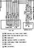
Note that the Honda circuit diagram shows this set up slightly differently. The wires coming out from the fuse box (Right side on the label photo, left side on thr rear view photo) are
Br/Bu (B)
Bl/Br (A)
W/G (E)
Bl (D)
Bl/Bu (G)
R/G (F)
R/Bl (C)
I find it odd that the power for all of these circuits are fed through a single 30A fuse - although when the alternator is running I don't think so much current will pass through it - the red/white alternator cable is connected directly to the red wire on the same side of the fuse.
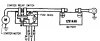
I wonder if retro-fitting the 40Amp alternator has some part to play in overheating issues ?

