Article [13] ST1300 - Gear Position Indicator (Do It Yourself)

Joined
Nov 13, 2007
Messages
13
Location
Burnsville, MN 55337
Re: My home-built DIY gear position indicator - includes plans

I finished building my GPI kit and attempted to do the final couple of install steps today, when I hit a bit of a snag. I previously had connected all inputs except the "Speed Sensor". Today, I attempted to locate the white, 3-wire connector in the weather proof boot, behind the canister purge solenoid, and make a connection to the "pink" wire. Unfortunately, I didn't find the connector or wire. I did find a "gang" of connectors in the weather-proof boot, but don't have any idea which one is the right wire? Connectors found were:
Grey - 10-pin; White (2-pin with grn./yel. &: grn./white wires); Black (3-pin with pink/black, green & pink/green wires); Grey (4-pin with green/pink, org./black, black/white & white wires); Grey (2-pin with brown/blue and org./black wires). I'm currently totally confused on which connector and wire I should be using?
I sure will appreciate any help anyone can give.

Thanks,
 
Last edited:

John Anthony

Moderator
Joined
Dec 3, 2004
Messages
2,136
Location
Seattle
Bike
'03 ST1300A
STOC #
5107
Re: My home-built DIY gear position indicator - includes plans

Does this photo help? If not, PM me with your phone number and a good time to call and I'll see if I can give you a hand. Once you get her up and running, this is a sweet little farkle!

John
 

Attachments

OP
OP
pdfruth

pdfruth

P.D.Fruth
Joined
Jan 28, 2005
Messages
242
Age
61
Location
Somewhere near Denver, CO
Re: My home-built DIY gear position indicator - includes plans

I finished building my GPI kit and attempted to do the final couple of install steps today, when I hit a bit of a snag. I previously had connected all inputs except the "Speed Sensor". Today, I attempted to locate the white, 3-wire connector in the weather proof boot, behind the canister purge solenoid, and make a connection to the "pink" wire. Unfortunately, I didn't find the connector or wire. I did find a "gang" of connectors in the weather-proof boot, but don't have any idea which one is the right wire? Connectors found were:
Grey - 10-pin; White (2-pin with grn./yel. &: grn./white wires); Black (3-pin with pink/black, green & pink/green wires); Grey (4-pin with green/pink, org./black, black/white & white wires); Grey (2-pin with brown/blue and org./black wires). I'm currently totally confused on which connector and wire I should be using?
I sure will appreciate any help anyone can give.
Thanks,
You are so close, you're on fire. :D

It's the black connector (not a white connector). Have a look at Page 25 (printed page 25) of the Install/Setup manual, attached to post #4, near the top of this thread. Page 25 is in part 3 of the 4 downloadable .pdf's. There's a really good picture of the connector, and it's wires, on Page 25 (the picture is captioned Figure 1.2.1b)
Mother Honda played a trick on us :) That black connector has a pink wire on one side that mates up with a pink/green wire on the other half of the connector. Have a look, I think it'll become very clear. If not, let me know.

Pat
 
Last edited:
Joined
Jul 21, 2007
Messages
2
Location
New York
Re: My home-built DIY gear position indicator - includes plans

Looking to see if any one is building these yet.Install will not be a problem for me but my electronics knowledge left me shortly after college some 25yre ago and boy have things changed.

Brian

07 ST1300
 
Joined
Nov 13, 2007
Messages
13
Location
Burnsville, MN 55337
Re: My home-built DIY gear position indicator - includes plans

I just got back from a "GPI Test Run", and it works GREAT! I would like to thank Pat for his spectacular work in making this project available to us. His kit, instructions and vast amount of supporting technical information are the best I have ever come across and made the project much easier than would normally be expected. He also was extremely helpful in getting me through my loss of one of the little red plastic LED package pieces that I let get away from me (my ST1300 "eats" little parts), and gave me a super-quick answer to my question about the location of the Speed Sensor wire (It was all their in his data, if I had been more through in my reading).
I ended up mounting the little electronics module in the small tool kit area, under the passanger seat. I mounted it under the auxiliary fuse panels that I had previously mounted in that area. It worked well, since the power and required input signals were already in that general area. I mounted the 7-segment LED display module on a small RAM ball mount that I was already using for my satelite radio. I used the 0.7" LED indicator and its viewability is excellent, even in direct sunlight. I also got the smaller 0.5" unit in case I ever get brave enough to try to mount it in the dash panel, as some braver souls have successfully done (always good to have another project for another day.

Again, my thanks to Pat.
 

Attachments

OP
OP
pdfruth

pdfruth

P.D.Fruth
Joined
Jan 28, 2005
Messages
242
Age
61
Location
Somewhere near Denver, CO
Re: My home-built DIY gear position indicator - includes plans

I just got back from a "GPI Test Run", and it works GREAT!
Ahhhh... another satisfied customer. Gotta love it. :D

Very nice. I especially like the connection between the black box and the display itself. I think you said you used a standard RJ45 jack and a flat RJ45 cable, yes? And the display brightness is adequate? I've wondered if that would work alright. I wonder what the voltage drop is, created by that long run? Have you measured it?

Thanks for posting up the pics... yet another install option for the masses.
 
Joined
Nov 13, 2007
Messages
13
Location
Burnsville, MN 55337
Re: My home-built DIY gear position indicator - includes plans

Ahhhh... another satisfied customer. Gotta love it. :D

Very nice. I especially like the connection between the black box and the display itself. I think you said you used a standard RJ45 jack and a flat RJ45 cable, yes? And the display brightness is adequate? I've wondered if that would work alright. I wonder what the voltage drop is, created by that long run? Have you measured it?

Thanks for posting up the pics... yet another install option for the masses.
Yes, I used a standard RJ45 jack, but used a 7 ft. (stranded, round, 24ga.) patch cord instead of a flat cable. I didn't make a voltage measurement, so I don't know what the volt drop was. However, based on the brightness of the LEDs, volt drop wasn't a problem.
 

st13fundred

Blue:The color of which place?
Joined
Apr 22, 2007
Messages
123
Location
Beaverton, OR
Bike
'04 ST13A
Re: My home-built DIY gear position indicator - includes plans

I used a standard RJ45 jack, but used a 7 ft. (stranded, round, 24ga.) patch cord instead of a flat cable.
Great job 07! The project box looks very professional.. Did you use one Molex connecor for 12V and Gnd, and a second connector for the "data signals"? Also, I'm trying to make out what is at the upper-left (outside) corner of the project box.

Again, it looks great, and am glad its working too! Thanks again, Pat, for the excellent work you put into this project!

Matt
 
Joined
Nov 13, 2007
Messages
13
Location
Burnsville, MN 55337
Re: My home-built DIY gear position indicator - includes plans

Great job 07! The project box looks very professional.. Did you use one Molex connecor for 12V and Gnd, and a second connector for the "data signals"? Also, I'm trying to make out what is at the upper-left (outside) corner of the project box.

Again, it looks great, and am glad its working too! Thanks again, Pat, for the excellent work you put into this project!

Matt
I used a 6-pin Molex connector for power, ground, ignition pulse generator (IPG), neutral and speed sensor (VSS) inputs. A 2-pin Molex connector was used for the light sensor wire & the RJ45 jack was used for the 7-segment LED output to the LED indicator. I also used another 9-pin Molex connector set in the front right inner cowl area, to permit future changes to the LED indicator, without changing any other cabling on the bike.
The item at the upper-left (outside) corner of the project box is a short piece of nylon tube that I used to mount the "Learn" switch on the outside of the box. The tube also prevents the switch from being accidetally pushed.
 

st13fundred

Blue:The color of which place?
Joined
Apr 22, 2007
Messages
123
Location
Beaverton, OR
Bike
'04 ST13A
Re: My home-built DIY gear position indicator - includes plans

I used a 6-pin Molex connector for power, ground, ignition pulse generator (IPG), neutral and speed sensor (VSS) inputs. A 2-pin Molex connector was used for the light sensor wire & the RJ45 jack was used for the 7-segment LED output to the LED indicator. I also used another 9-pin Molex connector set in the front right inner cowl area, to permit future changes to the LED indicator, without changing any other cabling on the bike.
The item at the upper-left (outside) corner of the project box is a short piece of nylon tube that I used to mount the "Learn" switch on the outside of the box. The tube also prevents the switch from being accidetally pushed.
Makes sense.. everything. Thanks for pointing out the details.

Matt
 
Joined
Oct 11, 2008
Messages
2
Location
Sweden
Re: My home-built DIY gear position indicator - includes plans

Hello

How do you connect your PICkit2 to the 18-pin 16F88

I have programmed many PIC:s but they have been 20-pin.
So I have used my low pin board to program.

I have tried many configurations but have not get it to
accept any program.

Best Regards
 
OP
OP
pdfruth

pdfruth

P.D.Fruth
Joined
Jan 28, 2005
Messages
242
Age
61
Location
Somewhere near Denver, CO
Re: My home-built DIY gear position indicator - includes plans

How do you connect your PICkit2 to the 18-pin 16F88
Here is the rig I use. The general purpose 40-pin Zif setup allows routing of the PICKit2 programmer's output signals to the requisite pins of the device being programmed.

In the case of the PIC16F88, you want to apply the PICkit2 signals to the following 16F88 pins;
VPP - pin 4
GND - pin 5
PGC - pin 12
PGD - pin 13
VDD - pin 14

Also, make sure that you configure the PICKit2 programmer software to use the "Use VPP First Program Entry" option. It's on the Alt->Tools menu.
 

Attachments

Joined
Oct 11, 2008
Messages
2
Location
Sweden
Re: My home-built DIY gear position indicator - includes plans

Here is the rig I use. The general purpose 40-pin Zif setup allows routing of the PICKit2 programmer's output signals to the requisite pins of the device being programmed.

In the case of the PIC16F88, you want to apply the PICkit2 signals to the following 16F88 pins;
VPP - pin 4
GND - pin 5
PGC - pin 12
PGD - pin 13
VDD - pin 14

Also, make sure that you configure the PICKit2 programmer software to use the "Use VPP First Program Entry" option. It's on the Alt->Tools menu.
Thanks for your fast answer have you changed R1 to another resistance
or is it original.

Regards
 
OP
OP
pdfruth

pdfruth

P.D.Fruth
Joined
Jan 28, 2005
Messages
242
Age
61
Location
Somewhere near Denver, CO
Re: My home-built DIY gear position indicator - includes plans

Thanks for your fast answer have you changed R1 to another resistance
or is it original.

Regards
Interesting you should ask... R1 on the Universal Programming Module is a 620 ohm resistor (if memory serves). It's the current limiter for the on-board yellow LED (not visible in the picture above) used to indicate when VPP is active.
I was having problems with the PICKit2 holding a steady/clean 5v VPP output. So I disconnected the LED, by unsoldering one end of the R1 resistor. In doing so, all my problems with VPP voltage level were thereby resolved.

Bottom line... to answer your question... I essentially removed R1 from the circuit, although it's hard to see that in the picture.
 
Joined
Oct 19, 2008
Messages
6
Location
Ballston Spa, NY
Re: My home-built DIY gear position indicator - includes plans

I've been chatting about this over on the RC51 forum. Thought I'd post over here, since the good folks of the ST community might find this interesting too. I'm never really sure which category to post into, so I'll stick it in the "General" section. Mods, please move this as appropriate.

I've undertaken a renewed interest in embedded micro-controllers lately. Over the past 20 years, I've puttered around with various MC's. I've worked with MC's such as - Intel 805x, Motorola 68xxx, 6502, and Zilog Z80. But never MicroChip PIC MC's. So, I wanted to educate myself on PIC MC's. This little project was simply a means to and end.... learn PIC16Fxxx microcontrollers, using a real-world application. And have something to show for it in the end.

It all started one day a few weeks ago. A buddy and I were talking (he has a Suzuki TL1000R)... he says "I wish I had a gear position indicator". I said "I think we can do that". So, after some research and development, I built him a GPI using a PIC16F88. Turned out to be a rather easy task. Since the Suzuki has a wire coming out of the transmission carrying a voltage ranging anywhere from 0 to 5 volts, depending on what gear it's in, I just used the PIC16F88's A/D converter to read the voltage, and convert it to a gear number. Once the gear number is known, it is a simple matter of displaying it on a seven segment LED, which is now velcro'd to the side of his instrument cluster.

Voila... Now he has a GPI, and I have a good bit of real world experience on PIC micro-controllers.


But noooooooo...that wasn't good enough, I was thinking.... Now I gotta have a GPI too.

So, I set out to build a GPI that'll work on my ST1300 and my RC51.
However, because Honda doesn't have a wire coming out of the transmission (like the Suzuki's do), a very different approach was required.

Here is the approach I took -
- Hondas have a vehicle speed sensor (mine do anyway), which emits a very nicely formed 5v digital square wave. The square wave's frequency varies in direct proportion with wheel speed, via a variable reluctance sensor coupled to one of the gears on the final output shaft (aka, counter-shaft).
- Hondas also have an Ignition Pulse Generator (IPG). The IPG emits a very nicely formed semi-square A/C signal. The frequency of the signal varies in direct proportion with engine speed, via a variable reluctance sensor coupled to the flywheel. There are exactly 12 pulses/cycles per crank shaft revolution.
- Hondas also have a neutral switch. When the bike is in neutral, the switch provides continuity to chassis ground.
- Hondas also have a clutch switch. When the clutch lever is pulled in, the switch provides continuity to chassis ground.

Given those four signals....
Using a PIC16F88 micro-controller, I've written code that essentially counts pulses, monitors the neutral & clutch switches, and outputs a result on a seven segment display. The micro-controller's on-board microprocessor, running at 4Mhz, does this over and over, very quickly (like a few hundred times per second). If the neutral switch is closed, I know to display a zero (my choice for indicating I'm in neutral). If the clutch switch is closed, I display a dash (my choice for indicating I'm between gears).
The core algorithm, essentially just counts pulses arriving from the speed sensor, and at the same time tallies up the number of ignition pulses that arrive for a given number of speed sensor pulses. Given this ratio of speed sensor pulses -to- ignition sensor pulses, it calculates which gear the bike is in, and displays that gear number on a seven segment display. Very easy, and very elegant.
I've also included an "Initialization routine" that allows me to put the code into "Learning" mode. The learning procedure essentially allows the user to tell the micro-controller, via interaction with a single pushbutton on the back of the display, how many gears the motorcycle has (cuz the ST1300 is a 5-speed, and the RC51 is a 6-speed). And then allows the code to "learn" how many IGN pulses per given set of speed sensor pulse for each gear. These learned values are then stored in nonvolatile EEPROM memory built into the micro-controller. Thus, this "learn" mode only needs to be performed once, upon initial installation of the GPI.

It took me a week or so to develop the code, and build a prototype. I just installed it on my ST, and took her for a spin (on a lunch break). I'm happy to report, it worked beautifully. Solidly indicates which gear I'm in at all speeds (up to legal limits, of course) and all engine RPM's.

I did do a fair bit of googling, to see if anyone else had done something like this. I found a few commercial offerings, but no home-brew stuff.
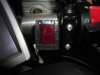
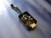
So, in case there are others out there with a propensity to do so, and are a little handy with a soldering iron... I thought I'd share the intellectual capital here. It's a pretty simple circuit. It only took me one night to build (once I had debugged it on a breadboard). With the exception of the micro-controller and the seven segment display, all the components are readily available at places like Radio Shack, Jameco, DigiKey, or Mouser. There's one IC (a PIC16F88 micro-controller), a seven segment display, three transistors, two diodes, a couple capacitors, a 5-volt regulator, and a hand full of resistors. The seven segment display turns out to be a critical component. The first one I used (out of the junk box) just wasn't bright enough to see on a sunny day. I eventually managed to find a super-bright red seven segment LED display at Kingbright (www.us.kingbright.com), and it is very visible in direct sun light.

I'll post a schematic, and source code for the micro-controller, in a few minutes.

Before anyone asks "Can you make me one", or "Will you sell me one"... I just wanna set expectations up front. This was just an experiment for me. Like I said, it was a means to an end. I built this thing using nothing more than a few junk box parts. I am in no position to start mass-producing GPI's. It is, however, my sincere hope that, by committing the intellectual capital to the public domain, and GPL'ing the source code, others will benefit. I also hope that other like-minded, talented, innovators out there will pick it up, improve/enhance/change it, and contribute those innovations back here to the community.

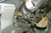
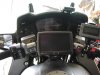
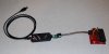
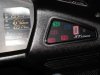
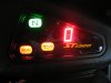
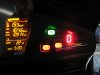
Here is a quick pic of the thing installed on my ST1300. The ST is sitting on the center stand, idling, in second gear (as can be seen on the display). The GPI display is velcro'd to the base of the handle bars, just back from the ignition switch.

Edit: 12/28/2008 -
Added updated circuit schematics & code for V1.3. Changes include the incorporation of a photo-cell, so that the seven segment display's intensity will automatically adjust according to ambient light conditions.

Edit: 2/8/2008 -
I've stocked up on all the components required to build the GPI. I can source individual parts and/or a complete builders kit.
I have 4 different types of builders kit. Each contains all the discrete components necessary to build a GPI, containing.... either;
1) External .8 inch LED display, with red acrylic display enclosure components, and ambient light sensor
2) External .8 inch LED display, with red acrylic display enclosure components, and no ambient light sensor
...... Note: see post #4 for an example of the prototype of the above two variations
3) In-dash .56 inch LED display (no display enclosure components), and ambient light sensor
4) In-dash .56 inch LED display (no display enclosure components), and no ambient light sensor
..... Note: see post # 154 and post # 161 for scoutdriver73's example of in-dash mounting.

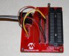
All builders kits now include the custom printed circuit board (see post # 166 below). The kit contains a blank circuit board, and all the discrete components necessary to build the circuit. The microcontroller comes pre-programmed with the latest version of the code. You get to solder "everything" together, and integrate it into your bike. See post # 4 below for a document containing the steps taken to install it on my ST.
I stock only RED superbright seven segment LEDs from Kingbright. And only the two sizes noted above. If you want a different size and/or color, you are on your own.

PM, or email, me with your needs. Prices and availability may vary, depending on my suppliers & supplier costs.

Should be easy enough - heck almost as easy as a Heath kit. Remember those?
 
OP
OP
pdfruth

pdfruth

P.D.Fruth
Joined
Jan 28, 2005
Messages
242
Age
61
Location
Somewhere near Denver, CO
Re: My home-built DIY gear position indicator - includes plans

....heck almost as easy as a Heath kit. Remember those?
Do I remember... heck ya. I've still got one of the Heathkit TV's, all the stereo stuff they ever made, a function generator, an LCR bridge, etc. etc...
Too bad they went away... those were good times :)
 

Blue STreak

Bob Meyer
Joined
Sep 6, 2005
Messages
1,388
Location
Fairfax, Virginia
STOC #
1157
Re: My home-built DIY gear position indicator - includes plans

Do I remember... heck ya. I've still got one of the Heathkit TV's, all the stereo stuff they ever made, a function generator, an LCR bridge, etc. etc...
Too bad they went away... those were good times :)
I used to have a bunch of Heathkit and Dynakit stuff. But kit built electronics make no sense anymore. Almost everything is surface mount, which really can't be soldered by the home user. Building a kit would amount to installing some circuit boards and plugging in some point to point wiring harnesses. Not much challenge or fun.
 

John Anthony

Moderator
Joined
Dec 3, 2004
Messages
2,136
Location
Seattle
Bike
'03 ST1300A
STOC #
5107
Re: My home-built DIY gear position indicator - includes plans

Barry,

Very nicely done. It looks terrific to boot. Couldn't agree more with you about the importance of taking your time on this project. Patience is rewarded with a nice result.

John
 
Joined
Mar 3, 2009
Messages
2
Location
United States
Re: My home-built DIY gear position indicator - includes plans

Good thing I have a degree in Electrical Engineering so this hits home! :) Did you use Maxplus to program the PIC?
 
Top Bottom