In case anyone needs it, here's the wiring diagram for Symtec heaters and a Heat Troller:
http://www.warmnsafe.com/motorcycle_handgrips.php
HTH!
http://www.warmnsafe.com/motorcycle_handgrips.php
HTH!

I'd wait for a return call from warm and safe but I'd bet :capwin:Here's what I've got:
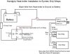
Symtec Heated Grips: Red, White, Blue wire from each grip pad.
Heat-Troller (HT): Red and Black (2 wires) with bare ends; blue and white (2 wires) with bare ends and a sheathed cable going to the switch & LED.
Shuey
I'd wait for a return call from warm and safe but I'd bet :capwin:
Red to postive power. (switched power from your acc fuse block or thru a relay if you don't have a fuse block)
Black to bike ground.
Blue is the + supply to the grip elements
White the ground return for the grip elements.
So;
Both elements red to the blue HT
Both elements white to the white HT.
Both elements blue wires unconnected.
iirc a 5amp fuse is more than enough for the HT while running the grips.
Chip, I get'em at my local ACE hardware in their little RV department.Woo Hoo.... Stopped by the local mom&pop auto parts just down the street... guess what... they have the SAE connector... And cheaper than on-line... I bought all they had!!!! Back to work!!!
The directions for the controller say perfect for DC motor control OR 12V light dimmer. Static test with 12V and ground to input, only meter at output, it shows, at full out, battery voltage. Turn it down a little and it goes to 11.7 V. Turn it down more and it drops to mv. Wonder if it needs load to make the IGFET work correctly?Not ringing a bell George maybe somthing like this LINK could be adapted.
I'd guess an RC controller would be looking for a pulse input to controll the output. 1ms pulse off 1.5ms half power 2ms pulse full out put the way a servo gets its control.