95 ST1100 timing issue

Need photo of cam lobes from TDC

the service manual pictures that have been posted multiple times show the same information as a picture would show.

The index lines are clearly identifiable as "lines" and the punch marks are clearly identifiable as "dots", cut into the ends of the cams.

With the crank at TDC #1 the index lines will be pointing outward on the right side cylinders, like in the diagram, and the punch marks will be pointing outward on the left side cylinders, like in the diagram.
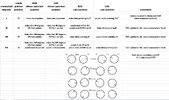
I agree with Doug; pictures are not necessary. As I posted before, the appearance of the cam ends at TDC are as Doug described and are clearly depicted in this schematic Martin posted in your other thread [if not, pull the belt and cams and install correctly]:

1773758227880.jpeg
 
Last edited:
OK, I decided to get creative on this and created a document that shows the positions of all 4 cams, at all 4 timing references. The 4 timing references are 0 (T1), 90 (T4), 360 (T1), and 450 (T4)

included in the document is a picture of the cam markings, and the driven sprocket markings. The driven sprocket also has a punch mark, which I never knew before. At 450 degrees the driven sprocket punch mark is aligned with the reference line. So, an easy way to reinstall the cams is to set the crank to 0 (T1) and make sure the driven sprocket line aligns with the reference line. Put in the RHS cams with the index lines pointing OUT. Then turn the crank 450 degrees, and verify the driven sprocket punch marks align with the reference line. Install the LHS cams with the index lines pointing out.

technical note: the document is an Excel s/s, but the forum apparently won't let me attach that type of file, only images. So, I did a couple screenshots of it and attached those instead.

John: if this is something we'd like to archive with other technical documents let me know, and I'll get it to you in s/s form.cam position screenshot.JPGindex and punch marks screenshot.JPG
This all assumes that the cams are in their proper place, i.e. not swapped int.-ex and/or right-left. All 4 cams have a different part #. What are the physical identifiers on the cams to tell them apart? This could be his issue also.
 
I … created a document that shows the positions of all 4 cams, at all 4 timing references

Very nice, Doug. I think we’ve provided Andrew all the info/help we can. Your screenshot image is more than adequate for our community. OTOH, it’s been literally years since I worked with a spreadsheet, but isn’t there a “save as” function where it could be converted to a .doc or .pdf version? In any case, thanks for this… well done!

Regards, John
 
This all assumes that the cams are in their proper place,
in the text I explained the simple two-step process to re-installing all the cams after they've been removed, that was the main point of my post since his cams appear to be hosed somehow.

this was the original text:

So, an easy way to reinstall the cams is to set the crank to 0 (T1) and make sure the driven sprocket line aligns with the reference line. Put in the RHS cams with the index lines pointing OUT. Then turn the crank 450 degrees, and verify the driven sprocket punch marks align with the reference line. Install the LHS cams with the index lines pointing out.

one additional piece of info that's generally known, but worth mentioning anyway is to achieve the 450 degree setting, starting at T1 0 degrees rotate the crank 360 degrees to T1 again, then another 90 degrees to T4.
 
it’s been literally years since I worked with a spreadsheet, but isn’t there a “save as” function where it could be converted to a .doc or .pdf version?
when I tried to save it as a PDF it jumbled the images around so the output document sucked.

Since a s/s supports text and images in a convenient format that seemed to be the best approach for now.
 
Back
Top Bottom