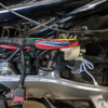
I wired a more direct connection from the battery to the coils on my bike and am just sharing what I did in case anyone is interested. I am not suggesting anyone has to do this.
On the ST1100, the path from the battery to the coils goes like this (with the associated voltage drop):
Battery --> 30A Main Fuse --> Ignition Switch --> 10A Ignition Fuse --> Bank Angle Sensor Relay --> Stop/Start Switch --> Coils
On my bike, after doing the ignition bypass relay mod, it looked like this:
Battery --> 30A Inline Fuse --> 40A Relay --> 10A Ignition Fuse --> Bank Angle Sensor Relay --> Stop/Start Switch --> Coils
Now I want to eliminate the Bank Angle Sensor Relay and the Stop/Start Switch, which will leave me with this:
Battery --> 30A Inline Fuse --> 40A Relay --> 10A Ignition Fuse --> (New Relay) --> Coils
To eliminate the B.A.S. Relay and Stop/Start switch (and also preserve their functionality), I would need an additional relay. Here is the ignition configuration before I started. Note that the 40-amp relay is from the previously done ignition bypass relay mod (link here). Click picture to enlarge:

Here's what it looked like afterwards (click to enlarge):

Since I had already had a connection from the battery directly to the fuse box via the 40A relay, I ran a 14 gauge, tinned, high-strand-count wire from the fuse box to a 20A relay up by the coils. I moved the existing black wire going to the bank angle sensor and the bank angle sensor relay to the new wire. I also had to move the alternator sense wire onto the new wire as well.
In hindsight, had I not already done the ignition bypass relay mod, I would have done this and not touched the fuse box:
Battery --> 10A Inline fuse --> 20A Relay --> 20A Relay --> Coils
This would have taken enough load off the "Red Wire" to make it a non-issue without having to mess with the fuse box. A twofer!
The only somewhat tricky part to this mod is digging into the harness and splicing the existing ignition wire plus the alternator sense wire into the new wire. Remove the tape from the harness in the area shown here; the sense wire/ign wire splice is wrapped in blue tape:

Unwind the tape to reveal the splice and cut where indicated:

Lay out new wire and strip off about two inches of insulation:

Crimp the ignition wire onto the new wire (NOTE: I added an additional wire here for a future project; it is not needed):

Then crimp the sense wire:

Tape the splice, then re-tape the harness with two layers of high temperature resistant electrical tape.


Use a good quality relay. Here I'm using a Panasonic/NAIS 20A relay.

I attached the relay to the area of the harness that runs under the crossmember just in front of the carburetor rack.

Then plugged the new wire into the fusebox.

On the ST1100, the path from the battery to the coils goes like this (with the associated voltage drop):
Battery --> 30A Main Fuse --> Ignition Switch --> 10A Ignition Fuse --> Bank Angle Sensor Relay --> Stop/Start Switch --> Coils
On my bike, after doing the ignition bypass relay mod, it looked like this:
Battery --> 30A Inline Fuse --> 40A Relay --> 10A Ignition Fuse --> Bank Angle Sensor Relay --> Stop/Start Switch --> Coils
Now I want to eliminate the Bank Angle Sensor Relay and the Stop/Start Switch, which will leave me with this:
Battery --> 30A Inline Fuse --> 40A Relay --> 10A Ignition Fuse --> (New Relay) --> Coils
To eliminate the B.A.S. Relay and Stop/Start switch (and also preserve their functionality), I would need an additional relay. Here is the ignition configuration before I started. Note that the 40-amp relay is from the previously done ignition bypass relay mod (link here). Click picture to enlarge:

Here's what it looked like afterwards (click to enlarge):

Since I had already had a connection from the battery directly to the fuse box via the 40A relay, I ran a 14 gauge, tinned, high-strand-count wire from the fuse box to a 20A relay up by the coils. I moved the existing black wire going to the bank angle sensor and the bank angle sensor relay to the new wire. I also had to move the alternator sense wire onto the new wire as well.
In hindsight, had I not already done the ignition bypass relay mod, I would have done this and not touched the fuse box:
Battery --> 10A Inline fuse --> 20A Relay --> 20A Relay --> Coils
This would have taken enough load off the "Red Wire" to make it a non-issue without having to mess with the fuse box. A twofer!
The only somewhat tricky part to this mod is digging into the harness and splicing the existing ignition wire plus the alternator sense wire into the new wire. Remove the tape from the harness in the area shown here; the sense wire/ign wire splice is wrapped in blue tape:

Unwind the tape to reveal the splice and cut where indicated:

Lay out new wire and strip off about two inches of insulation:

Crimp the ignition wire onto the new wire (NOTE: I added an additional wire here for a future project; it is not needed):

Then crimp the sense wire:

Tape the splice, then re-tape the harness with two layers of high temperature resistant electrical tape.


Use a good quality relay. Here I'm using a Panasonic/NAIS 20A relay.

I attached the relay to the area of the harness that runs under the crossmember just in front of the carburetor rack.

Then plugged the new wire into the fusebox.

Last edited:
