I'm am planning a long trip next year that will find me in the boonies from time to time, so I figured it was time to address the red wire issue that plagues the ST1100.
It appears there are two approaches; the "red wire bypass" and the "ignition relay bypass". The "red wire bypass" really does nothing other than trade one crimp for another. While this may work for a while (or long enough), it does not fix the issue. That 16 gauge red wire is still carrying all the current to power the bike, and I have read about people still having problems with melting connectors even after doing the red wire bypass. The ignition relay bypass actually fixes the issue by taking some of the load off of the red wire. Since I didn't want to have a nagging doubt about the red wire in the middle of nowhere, I decided to go with the ignition relay bypass method.
Norm Keller's excellent article in the AOW (http://www.st-riders.net/index.php?topic=3643.0) explains how the ignition relay bypass mod is implemented, so I'm only going to cover what I did differently.
On the '98 ABS/TCS, there are four fuse box supply wires that are switched through the ignition:
Wire 1: ABS Main (10A, Red/Black)
Wire 2: Fan Motor (10A, Blue/Orange)
Wire 3: Position, Meter Light, Tail, Neutral, Oil, Temp, Tacho, Horn (10A, Red/Black)
Wire 3: Ignition, Starter, Alternator (10A)
Wire 3: Turn Signal, Brake (10A)
Wire 4: Accessory (5A)
I decided to bypass wires 1, 2, and 3 and use wire 4 to energize the relay.
I didn't want to cut the three wires at the fuse box and use butt connectors, so that meant obtaining the right fuse box terminals. I located a source for the single fuse connectors (Eastern Beaver) but they didn't have the bused connector for wire 3. I thought I had found a source for the bused connector (https://www.amazon.com/gp/product/B079FPBDW7/ref=ppx_yo_dt_b_asin_title_o05_s00?ie=UTF8&psc=1) but as you'll see in the picture below, what they sent me was something different than what is pictured for that item on Amazon. But I was able to modify it to make it work.
I didn't use anything that came pre-crimped.
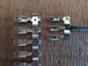
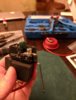
On the right is the bused strip of three connectors that I made from the strip on the left that was shipped to me:
Yes, I could have used three single connectors in place of the bused connector, but then I would have had five wires coming back to the relay and I didn't want that.
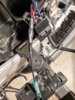
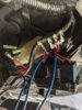
Here, the new wires (14 gauge) are installed in the fuse boxes after removing the existing connectors:
I taped and shrink wrapped the removed connectors to insulate them:
Doing it this way makes the mod easily reversible although I don't know why anyone would want to do that.
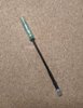
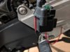
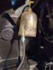
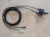
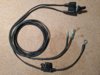
I put a 90° bend in the ring terminal at the starter relay so that the rubber cover would fit over it (used 12 gauge wire):
Crimped the male part of a bullet connector onto the wire going to the accessory circuit:
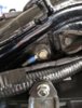
For the relay ground, I used the bolt behind the handle that is used to lever the bike onto its center stand.
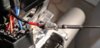
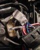
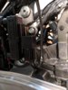
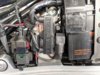
There's not much room between the alternator fuse and the battery to fit a relay, but the 40 amp sealed mini relay and base holder from Cycle Terminal (http://www.cycleterminal.com/accessory-relays.html) fit perfectly and I was able to mount it using the bolt to the right of the alternator fuse:
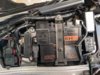
Here's what it looks like all buttoned up. I shrink wrapped the relay to keep moisture out:
I did not think to measure the voltage drop before I started, but I measured after I was done and it was only 0.06V between the battery and the fuse box.
Jeff
Edit:
For those without the accessory circuit (the 28-amp alternator bikes), here is a way to get switched power for the relay without cutting a fuse box wire.
Take a short piece of wire and crimp a male spade connector on one end and a female bullet connector on the other:

Push the spade connector onto the fuse terminal of the Red/Black wire:

Tape tightly and shrink wrap:

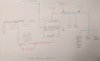
Rough diagram of Mod:
It appears there are two approaches; the "red wire bypass" and the "ignition relay bypass". The "red wire bypass" really does nothing other than trade one crimp for another. While this may work for a while (or long enough), it does not fix the issue. That 16 gauge red wire is still carrying all the current to power the bike, and I have read about people still having problems with melting connectors even after doing the red wire bypass. The ignition relay bypass actually fixes the issue by taking some of the load off of the red wire. Since I didn't want to have a nagging doubt about the red wire in the middle of nowhere, I decided to go with the ignition relay bypass method.
Norm Keller's excellent article in the AOW (http://www.st-riders.net/index.php?topic=3643.0) explains how the ignition relay bypass mod is implemented, so I'm only going to cover what I did differently.
On the '98 ABS/TCS, there are four fuse box supply wires that are switched through the ignition:
Wire 1: ABS Main (10A, Red/Black)
Wire 2: Fan Motor (10A, Blue/Orange)
Wire 3: Position, Meter Light, Tail, Neutral, Oil, Temp, Tacho, Horn (10A, Red/Black)
Wire 3: Ignition, Starter, Alternator (10A)
Wire 3: Turn Signal, Brake (10A)
Wire 4: Accessory (5A)
I decided to bypass wires 1, 2, and 3 and use wire 4 to energize the relay.
I didn't want to cut the three wires at the fuse box and use butt connectors, so that meant obtaining the right fuse box terminals. I located a source for the single fuse connectors (Eastern Beaver) but they didn't have the bused connector for wire 3. I thought I had found a source for the bused connector (https://www.amazon.com/gp/product/B079FPBDW7/ref=ppx_yo_dt_b_asin_title_o05_s00?ie=UTF8&psc=1) but as you'll see in the picture below, what they sent me was something different than what is pictured for that item on Amazon. But I was able to modify it to make it work.
I didn't use anything that came pre-crimped.
On the right is the bused strip of three connectors that I made from the strip on the left that was shipped to me:
Yes, I could have used three single connectors in place of the bused connector, but then I would have had five wires coming back to the relay and I didn't want that.
Here, the new wires (14 gauge) are installed in the fuse boxes after removing the existing connectors:
I taped and shrink wrapped the removed connectors to insulate them:
Doing it this way makes the mod easily reversible although I don't know why anyone would want to do that.
I put a 90° bend in the ring terminal at the starter relay so that the rubber cover would fit over it (used 12 gauge wire):
Crimped the male part of a bullet connector onto the wire going to the accessory circuit:
For the relay ground, I used the bolt behind the handle that is used to lever the bike onto its center stand.
There's not much room between the alternator fuse and the battery to fit a relay, but the 40 amp sealed mini relay and base holder from Cycle Terminal (http://www.cycleterminal.com/accessory-relays.html) fit perfectly and I was able to mount it using the bolt to the right of the alternator fuse:
Here's what it looks like all buttoned up. I shrink wrapped the relay to keep moisture out:
I did not think to measure the voltage drop before I started, but I measured after I was done and it was only 0.06V between the battery and the fuse box.
Jeff
Edit:
For those without the accessory circuit (the 28-amp alternator bikes), here is a way to get switched power for the relay without cutting a fuse box wire.
Take a short piece of wire and crimp a male spade connector on one end and a female bullet connector on the other:
Push the spade connector onto the fuse terminal of the Red/Black wire:
Tape tightly and shrink wrap:
Rough diagram of Mod:
Last edited:
 .
.