No, you got me wrong I am having a bit of difficulty of expressing my self correctly, since English is not my mother tongue. (sorry

What I did is almost as what you did in the first post.
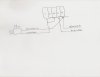
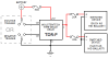
1. I cut the Black/Red and Blue/White wires as per your post.
2. To the side of the plug (to the left, as per your photo) I connected the the Black/Red to the 1 and +12 of the TDR(after making a 2 lead cable as per your photo)
3. To the side of the plug (to the left, as per your photo) I connected the Blue/White to the G of the TDR.
4. To the other side of the cut wires (the side that goes to the front of the bike, to the right as per your photo) I connected the Black/Red wire to the L of the TDR.
5. To the other side of the cut wires (the side that goes to the front of the bike, to the right as per your photo) I connected the Blue/White wire to the G (2 wires now on the G) of the TDR.
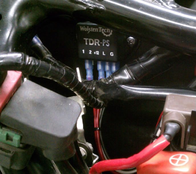
Maybe this picture gives you a better idea of what I have done
I have not used the SPDT switch as yet, I am just trying to see how to make the TDR work correctly. Also I am not sure that the 9Amps load from the Halogens is so hugely different from the 6 Amps load of the HID's and the TDR will also get heated. I still think I am connecting something wrongly.
As you have previously said the TDR works as a normal relay. Do you know what is the relation between the numbers found on a normal relay (30,85 etc) to the ones on the TDR?
I am also thinking, that if the heat problem continues, to use the TDR to trigger another normal relay. You think this is correct?

![IMG_0010[1].jpg](/forums/data/attachments/24/24158-ed8320e943d651ab2c64a51f754534a4.jpg)
![IMG_0011[2].jpg](/forums/data/attachments/24/24159-dc4a5eb5981e293de3d32fe4c6bc76cc.jpg)