I just took a look at my bike, just finished the complete installation, I don't believe it will fit there. Also the cable will be to short to reach where it need to go...Is the space behind the ST1300's left side panel (open area on 2003-2007) just ahead of the rear shock adjuster knob large enough to house the control unit?

You are using an out of date browser. It may not display this or other websites correctly.
You should upgrade or use an alternative browser.
You should upgrade or use an alternative browser.
Article [13] ST1300 - Rostra Cruise Control Installation
- Thread starter altexst1300
- Start date
I am writing this for others that may look at this and be intimidated by the wiring instructions. I really appreciate all that have contributed to this thread as each post has helped me get to the point where I finally bit the bullet and did the deed. I will add some of my insights and pictures that may help others.
I had previously installed the vacuum type of cruise control so I was not worried about the mechanical aspect. The wiring was my worry.
First there are wires on both the cruise control unit (CC) and the Goldwing switch (GWS) that are not used. These I wrapped carefully with electrical tape, some I cut shorter for convenience. The Centrodyne divider had all wires connected. In the next few paragraphs I will try to list each wire from each unit and where it attaches.
I will use the following abbreviations for colors.
Black- Bl
Blue- Bu
Brown- Br
White- W
Red- R
Yellow- Y
Gray- Gy
Green- G
Violet- V
Sky Blue- SBu
Light Green- LtG
Orange- O
Light Blue- LtBu
Pink- P
CC (cruise control unit)
Gy- to W on Centrodyne divider
Bu- to Bu on the left coil or Bu/Y on the right coil
Br- to a 12v switched + from the Quartet harness (Q) or other (+) source
Bl- to ground in Q harness or other (-) source
V- to brake switch cold, G/Y from 9 pin connector from right handlebar switch
R/Br- to Bl/G from GW switch
G- to W/Y from GW switch
Y- to W/Bu from GW switch
O- not used
LtG- not used
J Auxiliary speed connector- not used
K 4 pin switch cut off and not used with GW switch
L 2 pin connector- not used
GW switch ( Goldwing switch- #35130-MCA-A21 with back light)
W- to Y/Bl in 9 pin connector
Bl/W- to Bl in 9 pin connector
G/Y- to G/Y in 9 pin connector, this is the brake cold wire
W/G- to Y/G in 9 pin
Br/R- to Bl/R in 9 pin
Y/R- to Y/R in 9 pin
Bu/W- to Bu/W in 9 pin
Bl/G- to CC- R/Br
W/Y to CC- G
W/Bu- CC- Y
Bl/Y- to (+) from Q (switched)
LtBu/Bl- to (+) from Q (switched)
G-to gound (-) from Q
Y/W- not used, available for another circuit on the reverse on/off switch
Bl/R- not used, available for another circuit on the reverse on/off switch
Br- not used, available for another circuit on the reverse on/off switch
Bl/Br- not used, available for another circuit on the reverse on/off switch
G/W – not used
Other end near GW switch
W/G- attached to brake switch
G/Y- attached to brake switch
Bl/Y- not used, capped off
G/W- not used, capped off
Centrodyne Unit
W- to Gy from CC
G- to P/G found at the 27 pin connector on left of bike under gas tank area
R- to (+) in Q harness
Bl- to (-) in Q harness
I will attach a copy of my wiring diagram.
All (+) sources should be switched, in other words no on when the key is off and each should have an in line fuse. I used the Quartet harness for most of mine.
My Centrodyne divider is set at divide by 2 and high gain and I did not clip off the #8 capacitor, the newer units may not need these settings.
My throttle grip needed to be cut off by about ? inch as the GW switch is wider.

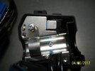
1. Goldwing Switch, note how much larger it is.
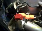
2. Here is the blue connector that has to be cut off.
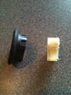
3. Inside you will note the small tab that requires the hole to be drilled in the handle bar to fit right.
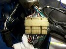
4. Last pic show the 4 wires near the switch end, two will go to the brake switch and two will not be used.
2. Here is the blue connector that has to be cut off.
3. Inside you will note the small tab that requires the hole to be drilled in the handle bar to fit right.
4. Last pic show the 4 wires near the switch end, two will go to the brake switch and two will not be used.
Attachments


Throttlejockey
Padden is my hero
Did you end up getting it to work smoothly below 60mph? I added a spacer to mine so I didn't have to cut the grip.
It will hold at 55 which will work just fine, very smooth.
More pictures to follow
More pictures to follow
Throttlejockey
Padden is my hero
It will hold at 55 which will work just fine, very smooth.
More pictures to follow
So, what did you change?
So, what did you change?
I used the settings you mentioned. Divide by 2 and full gain. I did not cut out #8 capacitor.
1. Tool you will need to make the Hitachi connectors. This shows the Centrodyne divider, I used a 4 pin Hitachi connector for it so it could be easily replaced.
2. Here is a picture of the 9 pin on the bike side after removing the standard handle bar switch.
3. I chose to use a 6 pin connector on the GW wires in addition to the 9 pin.
2. Here is a picture of the 9 pin on the bike side after removing the standard handle bar switch.
3. I chose to use a 6 pin connector on the GW wires in addition to the 9 pin.
Attachments


1. Note the small mark on the handlebar. The new GW switch was put on and then twisted, marking the metal, thus showing where the hole should be drilled.
2. Amount cut off the grip tube and the hand grip.
3. Old inner tube use as a waterproof cover for the Centrodyne divider.
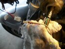
4. Tapping into the blue wire at the coil, I mated the wires together at the connector.
2. Amount cut off the grip tube and the hand grip.
3. Old inner tube use as a waterproof cover for the Centrodyne divider.
4. Tapping into the blue wire at the coil, I mated the wires together at the connector.
Attachments


1. The illusive pink/green wire at the 27 pin connector.
2. Closer.
3. isolated
4. I chose to remove the pin from the connector and then wrap and solder my wire to the pin and then replace it. Removing it was a little tedious.
2. Closer.
3. isolated
4. I chose to remove the pin from the connector and then wrap and solder my wire to the pin and then replace it. Removing it was a little tedious.
Attachments


Also, please check out this thread if you decide to tackle this project, it may save you some real problems...
https://www.st-owners.com/forums/showthread.php?115913-Near-miss!!!-Fuel-Tank-Hose-Leak
Again thanks to all that have contributed to this thread. I just wanted to contribute my experiences. I love the cruise.
https://www.st-owners.com/forums/showthread.php?115913-Near-miss!!!-Fuel-Tank-Hose-Leak
Again thanks to all that have contributed to this thread. I just wanted to contribute my experiences. I love the cruise.
fiziks
I brake things.
I was sent a different pulse divider than any pictured. Think it's an updated version. Did a divide by 2 and set the other pin on position B. It works great!!!! See pics of new divider. Getting errors on uploading will try later
How did you determine to put the jumper on "B" on the Centrdyne unit? Mine came with no instructions. The Divider jumpers seemed to be kinda obvious, but the "A", "B", "C" jumper are not.
Post a close up picture of the unit and maybe someone can help....
fiziks
I brake things.
I opened up my divider and it is yet a different design. I might post a picture tonight. There is a jumper block for the divider factor (1, 2, 4, etc) and the second jumper block is labeled "GAIN" and has 5 positions labeled from "LOW" to "HIGH". So, I'm curious as to what the "A","B","C" jumpers were in djdn's picture (perhaps it was a first pass at a gain jumper block). I'm also curious as to why folks have been clipping the C8 capacitor on the older models and my unit has a C8 capacitor (djdn's unit did not).
EDIT: My suspicion is that on earlier models with gain jumpers, clipping the C8 cap was the method for increasing gain. With the jumpers, gain is mre variable and C8 does not need to be clipped (clipping C8 would be the same as shorting the max gain jumper). But I could be wrong. It's been known to happen.
EDIT: My suspicion is that on earlier models with gain jumpers, clipping the C8 cap was the method for increasing gain. With the jumpers, gain is mre variable and C8 does not need to be clipped (clipping C8 would be the same as shorting the max gain jumper). But I could be wrong. It's been known to happen.
Last edited:
Throttlejockey
Padden is my hero
I set mine at high and divide by 2. No need to clip the C8 anymore according to Centrodyne.
fiziks
I brake things.
A couple things of note. I found the instructions in post #1 to be quite helpful. I also found it useful to read all the other Rostra Cruise Control Installation posts in the ST1300 Mods section. I did the throttle cable installation last night and the one thing that would have been helpful would have been measurements on the bracket and throttle arm extension.
My first attempt at a mounting bracket (using 1/16" x 3/4" x 3/4" aluminum "L" described at the bottom of page 5) proved to be too tall, and getting at the throttle cable nut that held it in place proved to be a real challenge, even after making a shorter bracket. So I mounted the bracket horizontally, instead of vertically with the CC throttle cable to the outside of the existing throttle cable. (I'll include a picture tonight when I get home). The bracket is about 1 1/8" wide. I used a 1/4" drill bit to cut the hole for the CC throttle cable and the "U" for the mount point (and then used a Dremel cutting wheel to cut out the rest of the "U").
As for the throttle arm extension... Instead of using a Futaba servo horn, I made an arm from one side of the 1/16" aluminum "L". Again, my first attempt was too long. My final attempt was just right. I used a 5/16" bit for the hole for the throttle drum shaft and a 3/16" bit for the hole for the throttle cable mount (I used the screw, two smaller lock-washer nuts, and eyelet connector included with the CC). the holes are approximately 1 1/4" to 1 3/8" from center to center. The total length of the arm was about 1 3/4". I used the Dremel to round and sand the end of the arm so that it would not cut into the breather hose over time, but it does not appear to be making any contact, which is good. I used a total of five beads from the bead chain.
Also, I skipped making a bracket (page 12) for the Cruise unit itself and bolted it directly to the frame in the same location as described. The included self threading screw is just the right size for the hole in the frame.
I hope these measurements help someone.
The head of one of the throttle body screws in the airbox was stripped, and tackling that (successfully) took more time than I expected, otherwise, I might have made it a lot further last night.
Last edited:
I am into the Rostra install with the dash mount switch. Got it all installed and passed the troubleshooting steps in the Rostra manual. The next test was to power up the bike and see if the Rostra would hold. Working with my brother we braced the bike and ran it up to about 40mph turned on the cruise waited for a few seconds and then tried to set the cruise.
test 1: With the blue wire from the Rostra connected to the yellow/green tach wire on the left side of the bike main connector the cruise would start to hold and then it would fo back
to idle.
test 2: with the blue wire not connected the cruise would rev from 0 - 6000rpm and repeat until shut off.
This was all done with the airbox off so we could watch what was happening. The futaba linkage is still holding. Just not able to get the Rostra to hold.
any suggestions? thanks for your help.
The blue wire goes to one of the coils,either right or left. On the left it would attach to the blue coil wire, on the right to the blue/ yellow wire. Check my wiring explanation or diagram a few posts back. I also show a picture of the blue wire attached to the left coil. From my picture it looks like the yellow/ green wire you used for connection is on the bottom side of the left coil. I would switch to the blue wire on the top.
Also I remember that some have said you can't test the bike on the stand? Maybe you could just temporarily lay things back together and take a short ride for the test.
Good luck...
Also I remember that some have said you can't test the bike on the stand? Maybe you could just temporarily lay things back together and take a short ride for the test.
Good luck...
Last edited:
Thanks, i'llmake that change and try a road test. Well let you know what happens.