
Article [13] ST1300 - Gear Position Indicator (Do It Yourself)
- Thread starter pdfruth
- Start date
I bought a kit - may have been a partial kit - that I no longer need. PM me if you are interested. I will check tonight and see what I have and maybe take a pic or two to send you if you want.So. As a really late person to arrive and discover this thread, my excitement built and then was crushed as I learned it was no longer available to buy as a kit form. Has anyone picked this up and moved forward? I don't have any problem with assembling stuff like this (would be a lot of fun), I have no idea how to get code programmed into a chip. Is this all still do-able...or am I relegated to spend $139 with a Healtech and have someone else do the work of putting it together?

Thanks again, Jim. I'll be looking forward to getting it and putting it together. Sounds like a lot of fun...hopefully minimal frustration. I just read through all 249 posts again, taking note and copying the manual pdfs.I bought a kit - may have been a partial kit - that I no longer need. PM me if you are interested. I will check tonight and see what I have and maybe take a pic or two to send you if you want.
I got the partial kit in the mail today. All the hard to find components there, including the programmed IC. Everything there but a cable and the circuit board. I got the same board from Radio Shack that the prototype used and discovered my soldering techniques are not as good as they once were. Before I go any further and do any harm, is there ANY possibility from ANYWHERE of getting the custom circuit boards that were made?
I cut the corners off the RS board, mounted the Power Supply IC, mounted the 18 pin socket, had a heck of a time just getting the fuse holder(s) mounted. I downloaded the manual, including pictures, and plan to plod along.
The other thing not in the kit was a 6' length of wire. Am I correct to think I can use a Cat 5 Ethernet cable for this? Any help is appreciated. I've been combing through this thread repeatedly and found a few helpful pictures in Bloodhound's gallery. Anyone point me to some other pictures for component placement?
the Ferret
Daily rider since May 1965
That looks so good. Wish Honda would have done that in the first place. Having ridden other bikes with a gear position indicator, I really miss it on the ST. Find myself riding for miles in 4 th before I discover I have another gear.
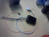
For those of you who installed this, I have a question. Not having a lot of faith in my soldering ability, I decided to power up the unit before installing it in the ST and risking damage there.
I temporarily hooked up the LED, the photocell, and the switch and connected it to a battery. Lo and behold, I got light and maybe I did it ok. The Clutch, Neutral, VSS and IPG wires are NOT connected to anything beyond the plug.
The problem: When powered up, the display flashes a repeated "6". No matter how long I wait, it never gives me a flashing "5". When I hold the Learn button as instructed (to select the 5 or 6 speeds), the display changes to a flashing "1", as expected, waiting for me to engage first gear. Off of the bike, that is as far as I can test it. Is there something wrong that I only see a flashing "6"? ...Or is this just because the other connections are not complete?
Thanks for any help....
OP
OP
pdfruth
P.D.Fruth
Sounds like you are very close to success.The problem: When powered up, the display flashes a repeated "6". No matter how long I wait, it never gives me a flashing "5". When I hold the Learn button as instructed (to select the 5 or 6 speeds), the display changes to a flashing "1", as expected, waiting for me to engage first gear. Off of the bike, that is as far as I can test it. Is there something wrong that I only see a flashing "6"? ...Or is this just because the other connections are not complete?
I would look for a construction error, or solder bridge. Something that results in the "e" segment of the seven segment LED being illuminated whenever one of the adjacent segments is illuminated (either "d", "f" or "g"). A likely suspect might be a bridge between pins 8 & 9 of the PIC.
Thank you, thank you! I really appreciate the response. That makes perfect sense to me! I'll get out the biggest magnifying glass I can find and hopefully find it! Soldering used to be easy to do, but at age 64 with tri-focals, this was a real test. I'm just glad I don't have my mom's palsy (yet)!Sounds like you are very close to success.
I would look for a construction error, or solder bridge. Something that results in the "e" segment of the seven segment LED being illuminated whenever one of the adjacent segments is illuminated (either "d", "f" or "g"). A likely suspect might be a bridge between pins 8 & 9 of the PIC.
Hip, hip, hooray! I checked the LED and found that there was a short, as you suspected. Then I checked the wires on the board and found that a and b had continuity (the LED is upside-down) and found a bridge across the PIC side of R10 and R11 (pins 11 and 12). Now I have a nice 5...6...5...6...etc. Can't wait to start the actual install on the bike! I owe you at least a beer if you get down to Havasu!Sounds like you are very close to success.
I would look for a construction error, or solder bridge. Something that results in the "e" segment of the seven segment LED being illuminated whenever one of the adjacent segments is illuminated (either "d", "f" or "g"). A likely suspect might be a bridge between pins 8 & 9 of the PIC.
OP
OP
pdfruth
P.D.Fruth
Excellent! Good to hear it's up and running.Hip, hip, hooray! ....... Now I have a nice 5...6...5...6...etc. Can't wait to start the actual install on the bike! I owe you at least a beer if you get down to Havasu!
Congrats
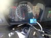
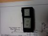
And running it is! I put the ST back together and made a sort of temporary mount for the LED and switch out of an end segment of a plastic pill box.Excellent! Good to hear it's up and running.
Congrats
Took it for a ride today and watched it work flawlessly. What fun! Thanks again for the hard work, Pat.
Attachments
-
 312.7 KB Views: 138
OK. I fiddled some more. Doing a little research on the Kingbright LEDs, I discovered SA39-11SRWA, which has all the same electrical specifications as the SA56-11SRWA that Pat kindly sent me, but is .39" rather than .56".
My original kit came with a SA56-11PBWA/A (a Blue one with different electrical specifications...Voltage at 3.3). The .39 blue version was hard to come by and has been on backorder for a long time. With Pat showing me that the Red one also worked (2.5 volts), I ordered a tiny red one from Mouser to try. It got here and I decided to try a different location.
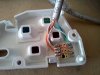
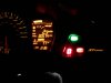
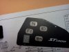
I have the non-ABS ST1300, so I took the white plastic piece and ground down the little focusing cone (for the non-existent ABS light) and mounted the little LED into that opening with a piece of the RS circuitboard (6 holes wide and 5 holes tall) and silicon. Then I used a razor blade to cut out an opening. This project is finally done. I used a cut CAT5 cable with a female-female connector in the middle for ease of installation for the 8 wire LED module.
Here are the pictures. Not shown, but I mounted the "learn" switch in the left mirror. Easy to get at if I want to reset the photocell threshold. I stuck the photocell in so it peeks through the louvers on the left, above the speaker grill. Works great!
My original kit came with a SA56-11PBWA/A (a Blue one with different electrical specifications...Voltage at 3.3). The .39 blue version was hard to come by and has been on backorder for a long time. With Pat showing me that the Red one also worked (2.5 volts), I ordered a tiny red one from Mouser to try. It got here and I decided to try a different location.
I have the non-ABS ST1300, so I took the white plastic piece and ground down the little focusing cone (for the non-existent ABS light) and mounted the little LED into that opening with a piece of the RS circuitboard (6 holes wide and 5 holes tall) and silicon. Then I used a razor blade to cut out an opening. This project is finally done. I used a cut CAT5 cable with a female-female connector in the middle for ease of installation for the 8 wire LED module.
Here are the pictures. Not shown, but I mounted the "learn" switch in the left mirror. Easy to get at if I want to reset the photocell threshold. I stuck the photocell in so it peeks through the louvers on the left, above the speaker grill. Works great!
Attachments
-
 296.9 KB Views: 86
 -
 80.1 KB Views: 118
 -
 203.4 KB Views: 75
 -
 213.4 KB Views: 98
Gus1300
Site Supporter
If I were to do this, I'd want it dash mounted similar to above. But I have an ABS. Looks like an interesting project. Might have to find space behind the same lens, maybe just above the ST if there's room there. Thanks for all the info here! Have been researching home grown PCBs, this might just be the project to do one with.
And I'd want to use this: http://www.lc-led.com/View/itemNumber/222. If anyone else is interested, their 'sample' lots run 15 pieces, I'd only need one. $20 and change for the first order, can distribute as desired for the other 14.
And I'd want to use this: http://www.lc-led.com/View/itemNumber/222. If anyone else is interested, their 'sample' lots run 15 pieces, I'd only need one. $20 and change for the first order, can distribute as desired for the other 14.
Last edited:
Brad, congratulations on a great job, and for persevering.
An especially nice touch in tracking down a much smaller LED to give you more location options. And to me, the smaller size cinches the OEM appearance. A truly unique and desirable addition.
I wish I had the wherewithal to seize the opportunity and see it to fruition. I'm jealous! Well done!
An especially nice touch in tracking down a much smaller LED to give you more location options. And to me, the smaller size cinches the OEM appearance. A truly unique and desirable addition.
I wish I had the wherewithal to seize the opportunity and see it to fruition. I'm jealous! Well done!
There is room above the ST1300. In this thread, and a couple others, you can find pictures of them by others. I just was hesitant to cut the big hole in that white plastic thing, as it is apparently only sold as part of the light board...for about $62. I did get a second Black sheet (about $4), and accidentally ordered the one with ABS. It helped as I had a better guide to see where to cut out the opening for the LED. So now the bike can be returned to normal with no visible evidence of my "tampering" if ever needed. As you can see from the picture, there is a section of that RS PCB that Pat identified that has just the right spacing for the tiny LED.If I were to do this, I'd want it dash mounted similar to above. But I have an ABS. Looks like an interesting project. Might have to find space behind the same lens, maybe just above the ST if there's room there. Thanks for all the info here! Have been researching home grown PCBs, this might just be the project to do one with.
That looks like a great idea. I am sure you could easily find a place to mount that in the black ST1300 plate. Maybe my next project. Looks like the same size LED and mounting as in the ACL head's up turn signal indicators. At $30, it is cheaper and much, much smaller than the Kuryakyn voltage thing that I have on the Magna. I think I "NEED" it...LOL.On a similar vein, is there room under that right side blank sheet to put a voltage monitor LED so that it seems part of OEM installation. I mean by drilling a small hole and poking it through?
I was particularly thinking for this voltage regulator:
View attachment 134997
http://signaldynamics.com/index.php/products/led-lighting?page=shop.product_details&flypage=flypage.tpl&product_id=56&category_id=44&vmcchk=1
If you look at my pictures in post #260 of this thread, you can see that I mounted the .39" LED essentially where the ABS light would be, if I had ABS. If you look at the white piece in conjunction with the black plate, you can see that you could mount this LED above the ST1300 OR in the middle of the cluster of the existing "idiot lights", or probably in a couple other places. The nice thing is that even tho you are altering that white plastic piece, which is part of the circuit board part and costs over $60, the black plate will cover it all up. The replacement black plates are less than $4. So if I ever sold the bike (to get a newer one, of course), I could remove the GPI and this voltage indicator and turn it back to a completely stock appearance for $4. You can't see the changes to the white plastic piece with the cover in place.