Anyone install the STS self cancelling turn signal module?

Joined
Sep 4, 2013
Messages
8,001
Location
Cleveland
Bike
2010 ST1300
A couple of questions if you have (I've not even taken the thing out of the box yet so some of these q's might be premature).

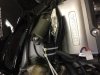
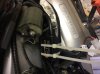
1. Where did you locate the module. It has to be horizontal and pointing forward for the accelerometer to work).

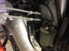
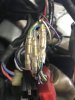
2. Where did you tap into the wiring harness? Any tips on id-ing the appropriate wires?
 
I removed the left fairing and spliced into the harness near where it passes under the brake line. I located the module on harness that is attached to the frame just in front of the left ignition coil. Sorry I did not take any pics. I will take some next time I remove the tupperware.

Wire colors on my 2007 are exactly as the instructions described. Installation was quick and the device works like a charm.
 
Last edited:
I located the module on harness that is attached to the frame just in front of the left ignition coil.

I'd sure like to see some photos CruSTy! Pete

+1 on wanting some pics

Here is where I'm (tentatively) locating my STS module - left side in front of the coil and strapped to the wiring harness. Is this where you put yours, CruSTy?
Anyone else think the fairing will hit it there?
That red and black wire with the white connector (Fuse 6 label) is a circuit I installed for my heated grips. I'll probably use it to power the STS as well.

Sorry about all the dupes of the same picture. I tried attaching them, they came out sideways so I deleted them, rotated them and tried again. Eventually got them oriented properly, and I thought I had successfully erased/deleted the sideways pics. Maybe Mellow will delete the sideways pics.

IMG_0567.jpgIMG_0566.jpg
 

Attachments

  • IMG_0566.jpg
    IMG_0566.jpg
    157.8 KB · Views: 138
  • IMG_0567.jpg
    IMG_0567.jpg
    163.3 KB · Views: 130
  • IMG_0567.jpg
    IMG_0567.jpg
    162.9 KB · Views: 135
Last edited:
Is this where you put yours, CruSTy?

Thanks for the pics. Give or take a centimeter that is were I placed mine. Streamlining all of the splices into the harness was the tough part.

I am generally pleased with the STS. The little foam pads in the turn signal switch were easy to install and work well to keep the switch detent from engaging. Not sure how well they will hold up over time.
This device does not always detect maneuvers from a simple lane change. Manual cancel is still required for those situations by signaling in the same direction a second time. Different process than the stock "push in to cancel".
 
Last edited:
I'm assuming there's no space in the front of the fairing behind the headlights? (Likely nothing to mount it on either)
Thanks for the pics, really appreciate it.


Sent from my iPhone using Tapatalk
 
This device does not always detect maneuvers from a simple lane change. Manual cancel is still required for those situations by signaling in the same direction a second time. Different process than the stock "push in to cancel".

Ahhh, so the unit does not time out after, say, 30 seconds? Tho if it works as advertised it will cut down on my flashing indicator signifcantly.

Seems to me that it should not be too difficult for a manufacturer to adapt what cars use. Attach a mechanism to the steering tube that cancels the signals whenever the handlebar is turned (either direction). Hard push on the switch turns them on, turning the fork switches them off. Or, just push and release and they flash only 5 times or so for a lane change. Just like our Toyota.
 
Last edited:
so the unit does not time out after, say, 30 seconds

So I reread the instructions and they state the unit will will cancel after 15 seconds if the maneuver is not detected (I will have to test this while riding). Also states if the bike is stationary it will not cancel the signal (I observed this).
 
Ahhh, so the unit does not time out after, say, 30 seconds? Tho if it works as advertised it will cut down on my flashing indicator signifcantly.

Seems to me that it should not be too difficult for a manufacturer to adapt what cars use. Attach a mechanism to the steering tube that cancels the signals whenever the handlebar is turned (either direction). Hard push on the switch turns them on, turning the fork switches them off. Or, just push and release and they flash only 5 times or so for a lane change. Just like our Toyota.

The difficulty with trying rig a mechanical self-canceller on a motorcycle is that the steer angle (the amount the forks and handlebars turn) in a typical manoeuvre is extremely small - likely not anywhere near enough for any sort of limit switch to detect.

That is why all bike units use some combo and/or distance, time or inertia signal like the STS.
 
The difficulty with trying rig a mechanical self-canceller on a motorcycle is that the steer angle (the amount the forks and handlebars turn) in a typical manoeuvre is extremely small - likely not anywhere near enough for any sort of limit switch to detect.

There's also counter steering to consider when making a turn about say 5-8mph. I think my 'Wing buddy's 2005 'Wing has self-cancelling turn signals but he usually cancels them. His BMW has has them and apparently they're just timed. I don't know what the interval is but the continue for maybe 15sec after every turn. Better than 10mi down the road but still annoying.
 
I've been using the STS unit for the past 4 months and here are some tips/observations to get it working flawlessly.

1) Install the STS unit in a location where it makes maximum contact with the frame of the bike. I have my unit ziptied behind the left meter panel.

2) When changing lanes, lean into your bike a little so it dips. After changing lanes, the bike is upright and the signal turns off. This has worked for me every time.
 
Pumper316 - can I ask where you made the electrical connections into the turn signal circuits?

Thanks for any suggestions.

Pete

My sincere apology for not taking pics when I installed. I had no idea there would be this much interest in the STS install. I just followed the harness from the left multi switch down behind the left upper fairing. The three wires you need are in that small harness. In addition you will need an ignition switched power and ground. The color coding on the STS instructions was spot on for my 2007. Not sure if there is variation from year to year or Europe for the wiring.
 
Last edited:
I'm in the process of building a custom harness to make mine more plug and play, and I had read a comment there may be some issues with Honda Motor cycles and the hazard system; I contacted STS on the concern, and my take away was they've programmed it to recognize hazard mode.
You are the first among all to notice that


Let me explain. You have two possibilities, whether you connect all wires, including hazard to brown, white and purple STS wires. And the other possibility is that you connect all the wires from hazard to the other side – blue, yellow and green STS wires. In second case the hazard function is no different as it is now. Just fort he first case we have programed hazard function in the STS, so when both inputs are held together, the STS turns on both outputs.


Usually we cut wires before they split to hazard and to turn signal switch. In that case you dont have to worry about hazard.
 
I'm in the process of building a custom harness to make mine more plug and play, and I had read a comment there may be some issues with Honda Motor cycles and the hazard system; I contacted STS on the concern, and my take away was they've programmed it to recognize hazard mode.

The only downside to my install is that my hazards no longer work after installing the STS unit.
 
The only downside to my install is that my hazards no longer work after installing the STS unit.

When was yours produced? The email I received yesterday claimed they've a programming mode that senses the dual inputs and allows a passthrough mode.
 
I'm in the process of building a custom harness to make mine more plug and play, and I had read a comment there may be some issues with Honda Motor cycles and the hazard system; I contacted STS on the concern, and my take away was they've programmed it to recognize hazard mode.

Hi Al-Hala: I'd sure like to see the details of that plug-n-play harness you are building - in fact, I am sure that we'd all like to see it!

Pete
 
I'll be happy to post up pictures once it is done. If it works out, it'll be a pass-through for a lot.

  • It appears the 9P RED connector (according to the manual) has the following in it:


  1. Orange from Hazard and Left Turn signal
  2. Blue from the Clutch switch (1/2)
  3. Light Green from the Horn Switch
  4. Light Green/Blue from the Screen Adjustment Switch
  5. Light Blue from the Hazard Switch and Turn Signal Switch (labelled SB on switch...)
  6. Light Green/Yellow to Screen Adjust Switch
  7. Green from the Turn Signal Switch
  8. Blue from the Clutch Switch (2/2)
  9. Pink/White from the Hazard Switch


Finding the connectors up here was fruitless; Digikey.ca actually failed me; Mouser was no better. I think they've something against automotive connectors in general.
I turned to the sources provided by ST-Owners: http://www.cycleterminal.com/110-connectors.html, http://www.vintageconnections.com/Products/Connectors, https://www.corsa-technic.com/category.php?category_id=53, http://www.easternbeaver.com/Main/Elec__Products/Connectors/110_Connectors/110_connectors.html.

Ordered through Vintage Connections: they had stock, were giving a discount to international (Canadian) shipments.

The concern I had was the Hazard switch is in parallel, and if the STS module didn't take into account IF both lines active THEN bypass and just let the lights strobe, I'd have to run wiring past the module, possibly damaging it if they didn't take precautions of blocking non-energized outputs from voltage. The communication I had seems to concur that they did, and I wouldn't need blocking diodes if I did want to bypass the module and put the Hazards directly on the output leads.
 
Back
Top Bottom