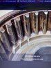
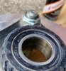
The wear on the Mr. E's spline is asymmetrical suggesting another factor being worn or damaged driven spline bearings which are fairly common on ST1300's. Owners have reported having to replace one or both in less than 20,000 miles. The driven spline is the male part and it rides on two sistered (side by side) 6905 RS bearings pressed into the driven spline flange. When the wheel is off for a tire or other maintenance it is most important to check these bearings. They carry no load in regard to the wheel and are out of sight inside the driven spline. Their job is to keep the driven spline and final drive in alignment. If the bearings fail to do this the driven spline will twist under acceleration / deceleration loads and wear the splines at each end of the machined spline and groove unevenly. Acceleration loads are by far greater and wear on the outboard end of the male spline (next to the O-ring at the base of the driven spline). Mr. E's pics show this type of wear. Deceleration loads barely wear the inboard end of the spline & polish the spline and groove out at the tip. Mr. E's spline shows such uneven wear at the outboard end while the inboard ends show not much more than polish. I wish I could find pictures of my ST's driven spline at high mileage but I do not have any that I could locate today. I make no comment on the type of grease or paste used or not used on the worn spline but the bearings were bad at some point in the history of this bike or perhaps now.
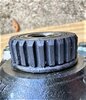
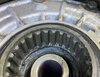
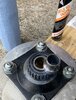
Picture 1 & 2 are of a low mileage driven spline I have had since 2006. Early in my 2005's ownership I bought the drive shaft, U joint, final drive pumpkin and rear wheel complete with flange and spline from a parted out 2004. All the parts were from the same bike. The bike was wrecked at very low mileage I believe under 2000 miles because the rear wheel weights had never been changed or moved and the OEM Dunlop 220 still had the nibs on it. Each time I changed a rear tire on my 2005 up to 175,000 miles I pulled the flange and driven spline that came with my 2005 and put it in the wheel w/new tire going back on. The wheel was alternated but the drive components never were. This way the driven spline and final drive splines in my bike always wore together as a matched pair. Every so often I replaced the two O-rings and rubber cush drive biscuits. The 2004's final drive components were never used and I still have them for these pictures.
Compare the nearly new splines with Mr. E's. The new ones have machined surfaces in parallel with ones to either side. Contrast with pics 3 & 4 and see the asymmetric wear from the spline twisting under load.
The book calls for just 3 grams of moly paste. I always use Honda Moly 60 paste and still have a 90% tube after using just one tube in the past. I use it now to lube the drive shaft splines of the BMW where they mate with the transmission and final drive. It will likely last me as long as I am riding. Pictures 5, 6, 7 relate to the brushes I use and how I coated the splines. One brush is for cleaning the old paste off and one for applying new past. 3 grams goes a long way. That's about three times what a person might apply of toothpaste to brush one's teeth. It's not much and just a thin even coat is what is needed. Too much and the male spline just pushes it out against O-ring and into the bottom of the female drive where it makes a mess to clean the next time. One load of paste on this brush would coat 3 or 4 splines, to be repeated until the male driven splines and female side ( final drive pumpkin side) are all done. Larry's picture above is perfection, my pictures is how I did it.
Picture 8 is the underside of the driven spline flange with the collar in the center. The cush drive biscuits fit in a circle around the center of the flange but they are missing in this picture. The collar must be pushed or tapped out from the other side to reveal the twin 6905 RS bearings pressed in the spline. Taking the collar out is the only way to check the final drive flange bearings. Picture 9 is of the collar out and sitting on top of the spline but it does insert from the underside. Picture 10 is a closeup of the two bearings in the spline.


.JPG")