St1100 Full Restoration Rebuild
- Thread starter Phil1164
- Start date
kiltman
Site Supporter
- Joined
- Apr 27, 2013
- Messages
- 3,270
- Age
- 68
- Location
- Stratford, Ontario Canada
- Bike
- 2002,ST1100ABS
- STOC #
- 8826
The two photos are from two different charging models. Post 81 is the 28 amp unit with the external Voltage regulator/rectifier. That increases the possibilities of malfunction. Check that white connector to the VRR. Also trace back the thre3 yellow wires to a red connector, check or. That main relay connector can also be an issue.
The fusible link is part of the 40 amp alternator circuit. Keep that as that is crucial when you upgrade the 28 amp alternator to the 40 amp unit. ( but I think you have acquired the post 96 engine with the 40 amp alternator or is that engine missing the alternator when you got it?)
The fusible link is part of the 40 amp alternator circuit. Keep that as that is crucial when you upgrade the 28 amp alternator to the 40 amp unit. ( but I think you have acquired the post 96 engine with the 40 amp alternator or is that engine missing the alternator when you got it?)
Yes Kiltman,
You are correct. Post 81 is a 1995 non abs aka standard model. The other photo with Fusible link intact is my 1999 abs (running) model.
I followed your advice and dug out the wiring diagram for the 95 Standard model. Am looking at page 22-2 from the Honda Shop manual.
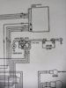
The white multi pin plug going into the reg rect is not damaged. The brass connectors inside the plug are shiny and corrosion free so have had a bit of good luck there.
Will follow the 3 yellow wires and also strip down the connection at the top rear of the main relay as there is rust on it. Thanks yet again for the advice.
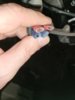
Have had to order a fusible link online. Thankfully found one with wiring included.
You know, I've assumed that the alternatior would be still attached but seeing as the bike has been butchered I best check and not take anything for granted.
You are correct. Post 81 is a 1995 non abs aka standard model. The other photo with Fusible link intact is my 1999 abs (running) model.
I followed your advice and dug out the wiring diagram for the 95 Standard model. Am looking at page 22-2 from the Honda Shop manual.
The white multi pin plug going into the reg rect is not damaged. The brass connectors inside the plug are shiny and corrosion free so have had a bit of good luck there.
Will follow the 3 yellow wires and also strip down the connection at the top rear of the main relay as there is rust on it. Thanks yet again for the advice.
Have had to order a fusible link online. Thankfully found one with wiring included.
You know, I've assumed that the alternatior would be still attached but seeing as the bike has been butchered I best check and not take anything for granted.
I've decided that some people need to stay away from tools and mechanical/electrical decision making.Houston, we have a problem!
Definitely found the problem or at least part of it.
There is no fusible link to the left of the battery. Well, I'm being my polite Canadian self when I say that. The truth being that there is no damn fuse board or its wiring either. It's completely stripped from the bike.
A swift swat across the nose with a rolled up newspaper usually does the trick!
I actually saw that during my military days. Poor kid was then removed from maintenance and became our new squadron clerk....where he did well.
Looks like you inherited the work from one such.
Consider it a challenge. I've rebuilt worse over the years, but with the assistance of a wreck or two.....and a lot more time to spread out the expenditures.Think someone has picked the best bits including tupperware and left me with a right pig's ear to sort out.
Am not giving up though. It's made me more determined than ever to see this through.
Hi Kiltman,The two photos are from two different charging models. Post 81 is the 28 amp unit with the external Voltage regulator/rectifier. That increases the possibilities of malfunction. Check that white connector to the VRR. Also trace back the thre3 yellow wires to a red connector, check or. That main relay connector can also be an issue.
The fusible link is part of the 40 amp alternator circuit. Keep that as that is crucial when you upgrade the 28 amp alternator to the 40 amp unit. ( but I think you have acquired the post 96 engine with the 40 amp alternator or is that engine missing the alternator when you got it?)
I've just re-read your last message. Are you saying that the fusible link in the black box as pictured on my 1999 daily didn't come with the bike in the first place?
kiltman
Site Supporter
- Joined
- Apr 27, 2013
- Messages
- 3,270
- Age
- 68
- Location
- Stratford, Ontario Canada
- Bike
- 2002,ST1100ABS
- STOC #
- 8826
Yes it should have come with your 99. It will also be needed in the event you upgrade the 95 to the 40 amp alternator. (Consult a wiring diagram for the two years and compare and you will see where that fusable link comes in on the 96-2002 model years)Hi Kiltman,
I've just re-read your last message. Are you saying that the fusible link in the black box as pictured on my 1999 daily didn't come with the bike in the first place?
I will admit to being confused as to which bike is being restored. For the most part the two bikes are the same EXCEPT the circuitry for the charging system, and a coolant line that is attached to the oil filter to cool the oil (1990-95) The 95 with the 28 amp alternator has the external VRR which gives you two more external connectors that can affect the proper running of the bike, those being the 6 wire white connector to the VRR, and the red connector for the three yellow wires coming out of the alternator to the VRR.
Both bikes will share an issue with the main relay red connector hence some will do the red wire bypass.
Another wiring issue that pops up, again model and country specific, is headlight circuit. If it was a 91-95 ABSI model, only one low beam headlight will illuminate, again refer to wiring diagrams for model and country to determine if that applies to the bike. The 99 model year I believe both low beams operate.
Thanks for the prompt reply Kiltman and yet again for the valuable information.
It's no wonder that you're confused as my head is spinning and it's me providing the information. Lol
The 99 ABS2 Burgundy is my daily ride.
The 95 with no plastics, amongst other bits and pieces, that looks like it's been dragged through a hedge backwards at 100 mph is the project.
I won't mention the bare frame that was acquired first as that would really muddy the waters for everyone reading this. Lol
I suppose that it's good news that it doesn't come with the fusible link as I can dive into it tomorrow with the lightsaber and look for dodgy wires/fuses.
Will definitely look at the other diagrams to compare the differences. Hopefully they will eventually make sense to me. Lol
John OoSTerhuis
Life Is Good!
Colo(u)red wiring diagrams: http://www.st-riders.net/index.php?topic=3908Will definitely look at the other diagrams to compare the differences.
John OoSTerhuis
Life Is Good!
Yeah, I printed out a couple of copies and carry one on the bike full-time.Thank you John.
That's a massive help. The colour coding makes a big difference.
John
- Joined
- Feb 5, 2005
- Messages
- 8,536
- Age
- 77
- Location
- Kingman, Arizona
- Bike
- 2000 ST1100 ABS TCS
- STOC #
- 004
I need to blow up the color diagram to wall size to help my old eyes. OTOH, I've got STerling all farkled so maybe won't have to go in again for a while.
Well the plot thickens...
I've removed the rear plastic mudguard and metal footpeg holder thingy as they were in the way.
The top four fuses in the fuse box are live on both sides. This includes the ignition circuit. The lower three fuses have no power at all.
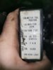
Which is odd as there is power to the ignition circuit but nothing happens.
Have traced the battery ground to the engine also and that is clean.
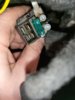
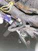
Following the three yellow wires to the alternator. Yes, it's still there.. I can see the wires go to a rubber boot. Under that boot is the bare metal of the 28 amp alt.
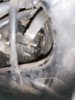
From looking online there should be a black plastic doo-dad and a connection for the wires but they're missing.
Not sure what is going on with it.
Also, have checked the starter relay with the ignition on and there is power to the left terminal/screw but not the right side. Is this normal or does it need replacing?
Any advice greatly appreciated as always.
I've removed the rear plastic mudguard and metal footpeg holder thingy as they were in the way.
The top four fuses in the fuse box are live on both sides. This includes the ignition circuit. The lower three fuses have no power at all.
Which is odd as there is power to the ignition circuit but nothing happens.
Have traced the battery ground to the engine also and that is clean.
Following the three yellow wires to the alternator. Yes, it's still there.. I can see the wires go to a rubber boot. Under that boot is the bare metal of the 28 amp alt.
From looking online there should be a black plastic doo-dad and a connection for the wires but they're missing.
Not sure what is going on with it.
Also, have checked the starter relay with the ignition on and there is power to the left terminal/screw but not the right side. Is this normal or does it need replacing?
Any advice greatly appreciated as always.
kiltman
Site Supporter
- Joined
- Apr 27, 2013
- Messages
- 3,270
- Age
- 68
- Location
- Stratford, Ontario Canada
- Bike
- 2002,ST1100ABS
- STOC #
- 8826
I need to look at wiring diagrams to do some tracing. In the meantime, take the right control switch off of the handlebars and open the two halves. Liberally spray contact cleaner inside where the switches are exposed, and work the switches. With the key on check to see if you’re getting power to the starter switch.
kiltman
Site Supporter
- Joined
- Apr 27, 2013
- Messages
- 3,270
- Age
- 68
- Location
- Stratford, Ontario Canada
- Bike
- 2002,ST1100ABS
- STOC #
- 8826
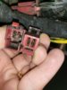
Please post a picture of the red connector to the main relay. I would like to see the inside of that connector please. Thanks
Did you replace that 30 amp fuse at the main relay?
Did you replace that 30 amp fuse at the main relay?
Yes, I replaced the green 30 amp blade fuse at the relay with no visible change.
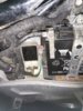
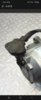
Here's a picture of me checking the relay's terminals with the lightsaber.
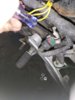
When I get home I'll open up the red connection into the relay and photograph it.
Is there a special way of opening it without breaking it?
Here's a picture of me checking the relay's terminals with the lightsaber.
When I get home I'll open up the red connection into the relay and photograph it.
Is there a special way of opening it without breaking it?
kiltman
Site Supporter
- Joined
- Apr 27, 2013
- Messages
- 3,270
- Age
- 68
- Location
- Stratford, Ontario Canada
- Bike
- 2002,ST1100ABS
- STOC #
- 8826
The red connector has been removed, instead they have individually hooked up the spade connectors. Pull the right front one inspect it. That’s the main red wire that we’ve been talking about. There’s a good possibility that it may be burned out.When I get home I'll open up the red connection into the relay and photograph it