St1100 Full Restoration Rebuild

kiltman

Site Supporter
Joined
Apr 27, 2013
Messages
3,270
Age
68
Location
Stratford, Ontario Canada
Bike
2002,ST1100ABS
STOC #
8826
Thank you, thank you.
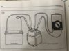
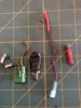
The connectors to the main relay look good. At one time the previous owner had an issue and he opted not to use the red connector housing, instead used individual spades which work just as well. Do you get power out of the red wire with the key on?
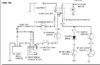
When you press the starter button do you get power at the yellow wire/red tracer at the main relay?
When you turn the ignition on do you hear the main relay click?
Many owners bypassed the red connector for the three yellow wires and instead used crimped connectors or soldered the three yellow wires individually to each other. If your plan is to upgrade the alternator just clean that connector up as you will not need those wires with the 40 amp unit.
At the ignition switch is a red wire with a blue tracer need to see if you get power to it ( with key on)
I couldn’t tell if your light Sabre lit up when you checked the main relay, please confirm you had power there.
Thanks
 
OP
OP
Phil1164
Joined
Oct 29, 2021
Messages
74
Age
52
Location
England
Thanks yet again for all your help Kiltman. I'd be lost without it.

Will do the other checks you mentioned as soon as possible but for now I can answer the question about the starter relay.

With the ignition on the lightsaber lit up on the left side only, towards the front end of the bike. The terminal on the right appears dead.
 

kiltman

Site Supporter
Joined
Apr 27, 2013
Messages
3,270
Age
68
Location
Stratford, Ontario Canada
Bike
2002,ST1100ABS
STOC #
8826
Also, there's no click from the relay when the ignition is turned on.
As you had suspected earlier, I think you’re correct that the main relay is faulty. Sorry I made you go through these tests but my observations, the relay burning out doesn’t happen to the same extent as the red wire burning out.
That’s not to say it will totally resolve the issue. The relay does provide power (when activated) to the clock, and starter circuits which would explain why you weren’t getting current at those locations on the fuse block.
 
OP
OP
Phil1164
Joined
Oct 29, 2021
Messages
74
Age
52
Location
England
No need to apologise Kiltman. You're helping me with this and as you've probably figured out I'm pretty much clueless when it comes to automotive electrical stuff. I appreciate the help and support from everyone.

Saying that I am enjoying learning how to read wiring diagrams and then tracing the route with the corresponding wires. The colour coded diagrams are so much easier to follow, especially now I'm refusing to get eyeglasses.

Guess it's time to start looking for a 40 amp alternator and a red wire bypass kit. Will the VRR need upgrading too?

Will order a new starter relay and update once its arrived.
 
Joined
Mar 13, 2012
Messages
5,054
Location
soCal
Bike
'97 ST1100
STOC #
687
Also, there's no click from the relay when the ignition is turned on.
I think we're talking about the starter relay, right? There shouldn't be a click when the ignition is turned on, you should only hear a click when you press the starter button
 
Joined
Mar 13, 2012
Messages
5,054
Location
soCal
Bike
'97 ST1100
STOC #
687
There's also a string of items in the path like sidestand switch, clutch switch, etc. so if it doesn't click upon pressing the starter button that doesn't mean the relay itself is bad. The wiring diagrams are needed for this task. this diagram may also help get the big picture. If the bike is in neutral, the neutral switch is closed and if the clutch diode is OK, the relay should click. the "engine stop" switch is the kill switch on the right handlebar by the starter button. If that doesn't work the other path needs the sidestand up and the clutch pulled in. Note that the bank angle sensor relay can kill the entire path, so that's the first place to verify you have 12v, at the kill switch terminal.


Capture.JPG
 
Last edited:

DaveWooster

'95 ST1100ALS and '98 Standard ST1100W
Joined
Oct 31, 2007
Messages
352
Location
Topeka, Kansas, USA
Bike
1995 ST1100A
STOC #
3480
...
What year is your bike? There are subtle differences; also there are two generations of the ABS system; knowing which one will also aid in the restoration.
The tenth character of the VIN of the frame gives its model year. The two generations of ABS are then:

Years up thru S: ABS I
Years T and later: ABS Ii

(But it is the year code from the VIN on the frame that is needed for this.)
 
OP
OP
Phil1164
Joined
Oct 29, 2021
Messages
74
Age
52
Location
England
I've plugged everything back into its counterpart and the green wire (ground) is mating tight to some bare metal on the frame.

I couldn't get the kill switch starter button unit open due to a stripped Philips head so that will have to wait til I'm off work.

I did check the engine/battery ground near the starter. There is some white/green crud on it where the exposed copper is but the lightsaber lights up when a connection is made to the bolt.

Same goes for the starter wire. No crud but is live.

Still nothing from the relay sound wise with the ignition on, kill switch in run position and starter button pressed.

One thing I noticed is that the LCD clock is on now but when the ignition turns to on the clock display goes out. Then when the ignition is switched off the clock comes back on and keeps time. It doesn't reset to 12:00.

A new relay has been ordered. Will update once it comes.

Am shopping for a 40 amp alternator if anyone has a working spare or knows of a website that does fair prices?
 

kiltman

Site Supporter
Joined
Apr 27, 2013
Messages
3,270
Age
68
Location
Stratford, Ontario Canada
Bike
2002,ST1100ABS
STOC #
8826
One thing I noticed is that the LCD clock is on now but when the ignition turns to on the clock display goes out
That’s typical of the red wire issue. I know I keep harping on it. On my 1990 unit when the connector burned out I had to strip back the insulation to get to shiny copper. It was all black and brittle for about an inch. I ended up splicing in a new section of wire. Have a look at how that female spade was attached to the red wire, possibly put a new one on and examine the condition of the wire.
dwalby also brought up a few other components. One being the side stand switch. I had a failure on both my 1990 and 97. there’s a green connector up and left of the main relay above the tip over bar. If you take the connector apart you can jumper two of the wires to complete the circuit to bypass the switch. ( I will edit later with the wires to jumper).

EDIT: added photo. Jump the green wire to the green and white.
 

Attachments

Last edited:
Joined
Mar 13, 2012
Messages
5,054
Location
soCal
Bike
'97 ST1100
STOC #
687
clock on with no load, off with load indicates you have a voltage drop due to corrosion somewhere in the path. the clock draws a very small current, so the voltage drop across the corrosion isn't significant enough to cause it to turn off. When you put a higher current load on the circuit, the voltage drop across the corrosion is substantial, and the clock no longer receives 12v at its terminal and turns off. You really need a multimeter to keep working this issue so you can measure voltage and resistance to get a better picture of what's going on, and where.
 

kiltman

Site Supporter
Joined
Apr 27, 2013
Messages
3,270
Age
68
Location
Stratford, Ontario Canada
Bike
2002,ST1100ABS
STOC #
8826
The last photo is what I carry on the road.
1st photo is my side stand switch bypass (jump green/white to green)
2nd photo helps me deal with a "Red Wire" issue I use the positap to connect to a solid point in the red wire and then with the female spade connect to the relay. (15 minute fix on the side of the road)
The item with the black tape around it is a homemade clutch diode. I have in the past hooked up the green/red wire wrong to the main relay which has blown the diode. (The diode is located on the left side of the airbox.
 

Attachments

OP
OP
Phil1164
Joined
Oct 29, 2021
Messages
74
Age
52
Location
England
clock on with no load, off with load indicates you have a voltage drop due to corrosion somewhere in the path. the clock draws a very small current, so the voltage drop across the corrosion isn't significant enough to cause it to turn off. When you put a higher current load on the circuit, the voltage drop across the corrosion is substantial, and the clock no longer receives 12v at its terminal and turns off. You really need a multimeter to keep working this issue so you can measure voltage and resistance to get a better picture of what's going on, and where.
I do have a multi meter, just never learned how to use it.
 

kiltman

Site Supporter
Joined
Apr 27, 2013
Messages
3,270
Age
68
Location
Stratford, Ontario Canada
Bike
2002,ST1100ABS
STOC #
8826
This may help you diagnose the starter relay.
There are 2 PDF files attached and one photo of diagram 143 that is referred to in the documentation.
Look at Starter Relay Click test (1st pdf)
look at Starter Relay Voltage Test (2nd pdf)
You can also do the Starter Ground test as well as the starter relay operational test (you need figure 143 for that test and that's what the photo is of.)

These instructions were taken from pg. 324-326 in the Clymers manual
In post #113 dwalby mentions corrosion. I'm thinking the likely spots are at the relay (which looks clean from the photos), the fuse box, and the ignition switch (the key unit at the top of the fork)
 

Attachments

Joined
Sep 10, 2011
Messages
2,210
Location
West Michigan
Bike
'98 ST1100
STOC #
8470
Thanks Erdoc,

The engine will be painstakingly reduced to its last bolt and the tolerances checked as I go. It will get all new bearings, journals, timing belt, water pump, etc as she goes back together.
Just curious - how many years are you budgeting for this project ? Any chance after 2 or 3 years you may decide not to finish the job ? If so, that would be 2 or 3 years of effort basically wasted. Not to throw water on this, but something to think about, IMHO.
 
Top Bottom