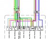
So,, bit of an update,, I went ahead and completed the (gulp) connections,,, as per the modified instructions. Cutting 4 wires total, in the switch harness, just above the red plug-in connector. It is far from a road test,,, as the forks are still off the bike, and we received 6" of snow today. But the flashers and hazards both work as would be expected. I did not need any extra connectors, as I just jammed both the pink and grey wires into a single connector on each side of the cut switch harness wires. The wad of connectors is going to need a weather proofing wrap of some kind. But those connectors seem to attach and plug in pretty firmly. Thanks to David,, for scratching up the new wiring info,, just in the nick of time,,, Cat'
ps: now on to the hd video recorder install !!